INSILIA2

THE EVOLUTION OF THE REVOLUTION
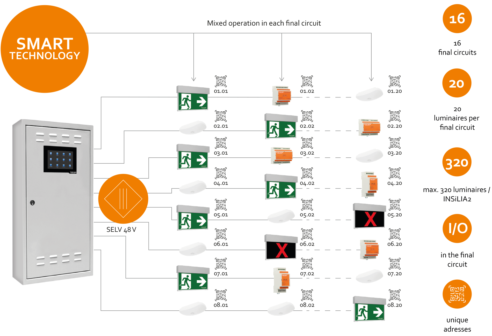
» Thanks to SMART technology, emergency luminaires can be operated in mixed operation on the final circuits
» Optional I/O modules can be used on the final circuit ike emergency luminaires.
This creates the possibility of monitoring general lighting luminaires without additional cabling
» Maximum load 120 W per final circuit
» Supply of up to 320 emergency luminaires
» 48 V system voltage allows up to 500 m final circuit length
» Unique addresses: automated address allocation via one unique address 
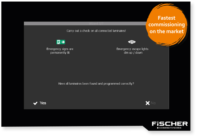
Wizard guarantees an easy start-up
As with its predecessor, the INSiLIA2 is started up automatically via the INSiLIA WIZARD.
» The luminaires installed on the circuits are recognized by the software according to their function
» In 7 simple steps, all connected escape sign luminaires are switched to continuous operation and all emergency luminaires are switched to stand-by mode
» The basic configuration takes place within 5 minutes
» The installer can name the luminaires in a free text field
| Commissioning time of LPS systems | |||||
| Quantity | 1 pcs | 2 pcs | 5 pcs | 10 pcs | 20 pcs |
| INSiLIA2 | 5 minutes | 10 minutes | 25 minutes | 50 minutes | 100 minutes |
| Competition | 15 minutes | 30 minutes | 75 minutes | 150 minutes | 300 minutes |
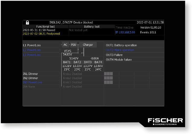
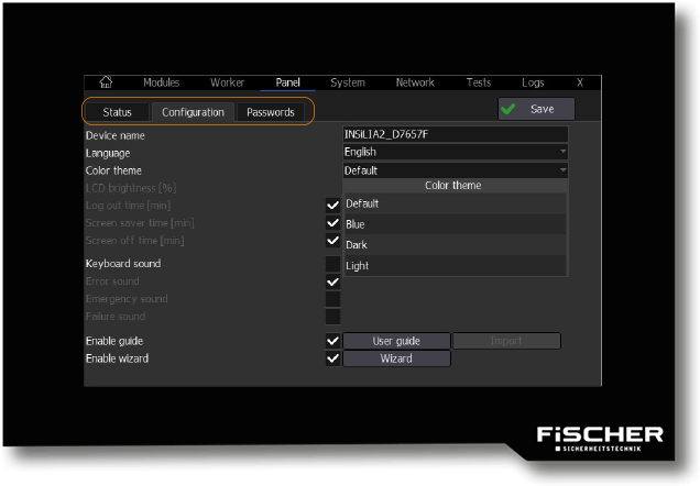
Operation
When it comes to operation, INSiLIA has always been able to set the standard. Evolution instead of revolution was therefore the requirement for the INSiLIA2. The known elements have been improved where necessary. Others have been added based on our experiences.
» Home screen: displays the most important parameters of the system status directly and clearly arranged
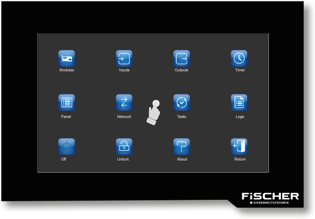
» Touch operation: sensitive 5,7’’ color display with high resolution, user interface in icon design
» TabView: facilitates the overview and speeds up the configuration
» Web browser/network connection: already included in the standard
» Status display of all luminaires and modules
(LED on ■, stand-by-mode ■, deactivated ■, switching status I/O module ■)
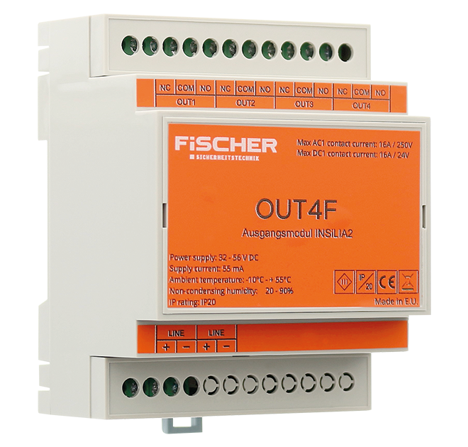
Optional I/O modules
The data transmission between the optional I/O modules and the INSiLIA2 system takes place via the same cable that also ensures the power supply. The modules are connected directly in the final circuit.
The OUT4F module is a universal output module for operation between electrical devices, the building management system, and the central battery system INSiLIA2. The module has 4 relay outputs for control or signal transmission between any devices.
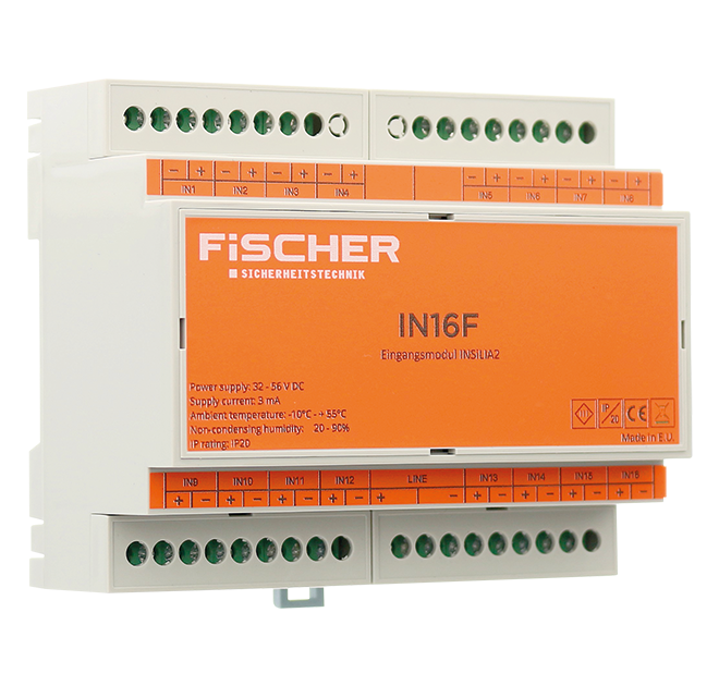
The IN16F module is equipped with inputs for communication between building installation devices and the INSiLIA2 central battery system. The module has 16 floating inputs with the ability to change the triggering logic.
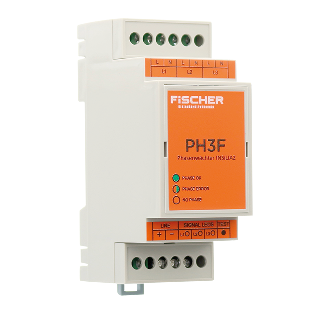
The PH3F module is used to monitor 230V AC potential signals. Depending on the user’s requirements, the device can be used as a phase failure sensor or to control the emergency lighting using a switch. It has 3 potential inputs with programmable triggering logic. The inputs can be programmed to separately monitor the individual protection functions of the general lighting circuits or as a 3PH phase failure monitor. The restart delay function can be assigned to each of the three inputs.
 |
 |
 |
|
| Technical specifications | |||
| output module OUT4F | input module IN16F | phase guard PH3F | |
| Inputs | – | 16, potential-free to connect | 3 separate inputs |
| Outputs | 4 | – | – |
| Functions | normally open (NO) or normally closed (NC)) | active, inactive, short circuit, interval | switch monitoring, monitoring of 3 phases |
| Communication | via the supply line | via the supply line | via the supply line |
| Mounting | TH-35 DIN rail | TH-35 DIN rail | TH-35 DIN rail |
| Dimensions (L x W x D) |
71 x 90 x 57 mm | 106 x 90 x 57 mm | 36 x 90 x 58 mm |
| Special features | » Monitoring of switches or the mains supply » 4 programmable relay outputs » Easy to install on TH-35 DIN rail |
»Up to 16 programmable control inputs (NO, NC, RSER, RPAR) » Easy to install on TH-35 DIN rail |
» Monitoring of switches or of the mains supply » Programmable input logic with restart delay » LED status display of each input »Easy to install on TH-35 DIN rail |
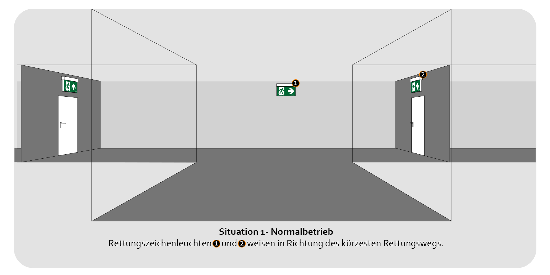
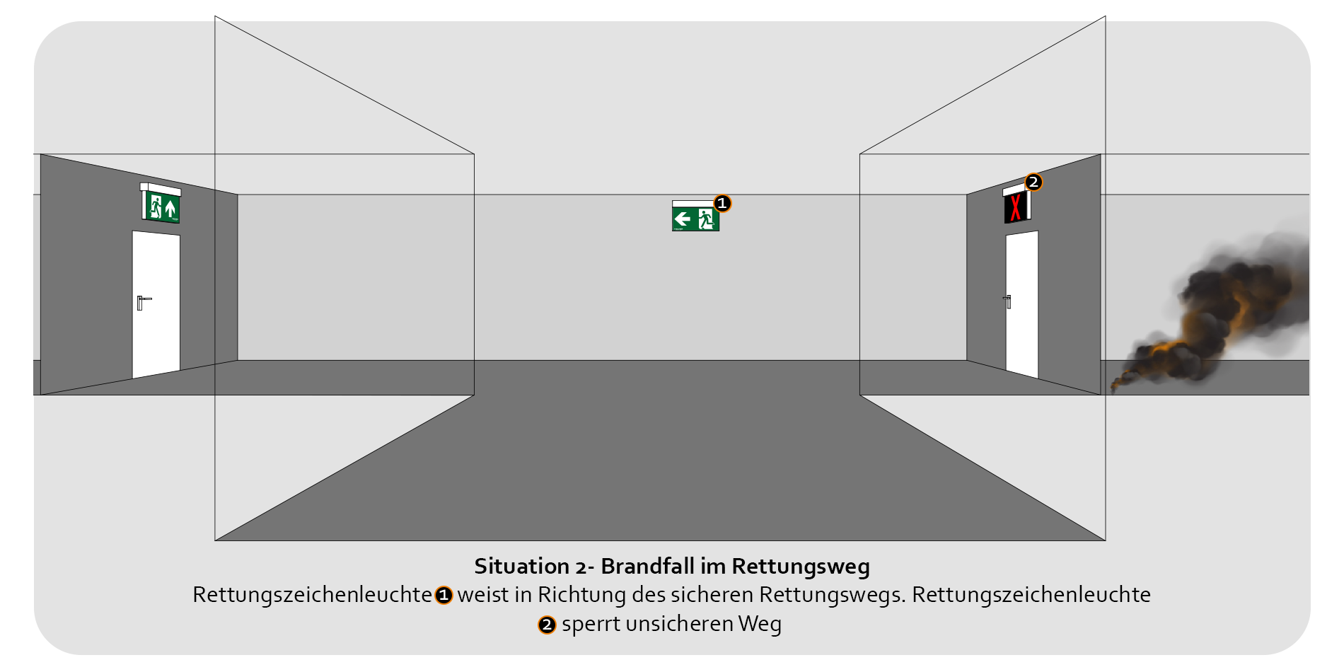
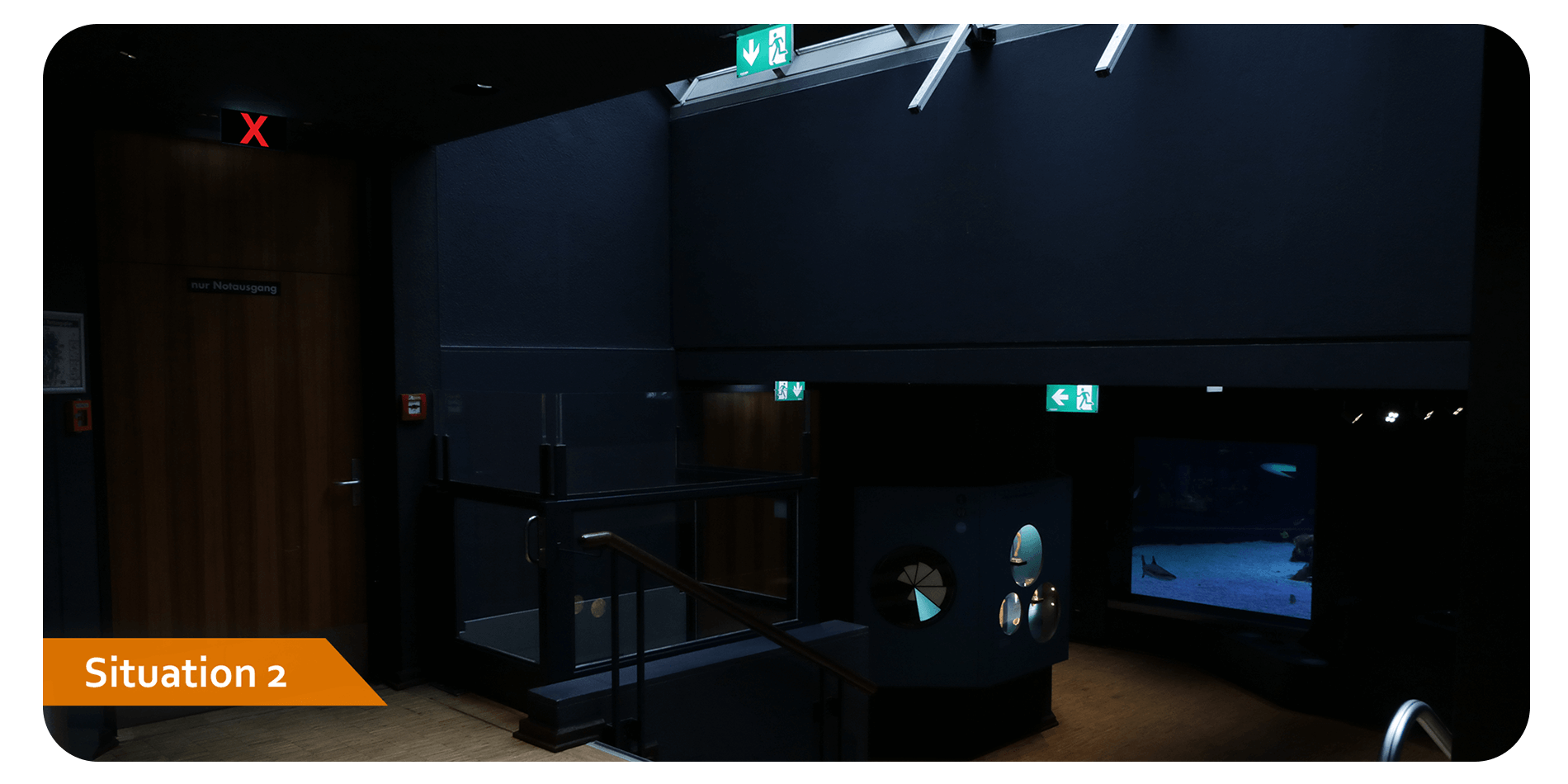
Dynamic escape route guidance
Traditional escape sign luminaires with a static function guide the way in an emergency. However, there are situations, such as a fire, in which the static display of the same escape route can be disadvantageous. Namely exactly when it is already full of smoke. In this case, it is safer to use dynamic escape route guidance, which can automatically adapt to the dangerous situation and indicate an alternative escape direction. If escape sign luminaires that are specially designed for dynamic escape route guidance are operated on the INSiLIA2 series, the system can switch the pictogram displayed on the luminaires depending on the dangerous situation.
The pictogram change of the luminaires is switched by the INSiLIA2 system according to information for example from the building management system. The system can display different escape route directions or a blocking symbol via the luminaires. The flashing function of the pictograms, which can be set on request, increases the attention of fleeing people even more.
Overview of pictograms that can be displayed:


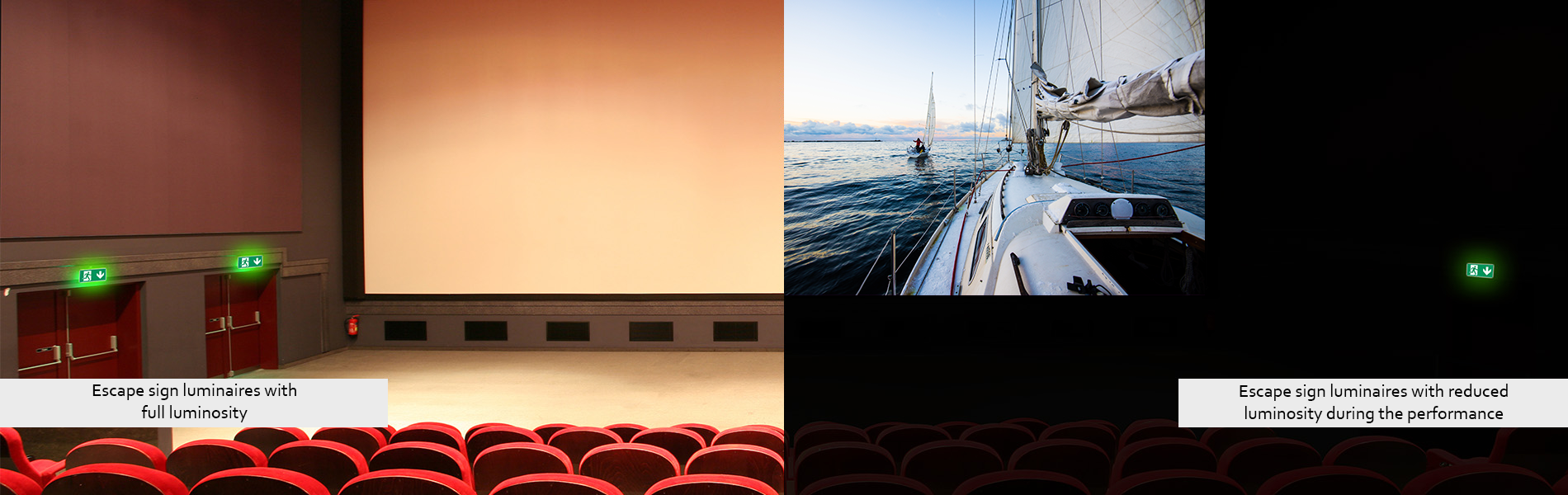
Dimmable emergency and safety luminaires
In places of public assembly
In operationally darkened rooms, for example movie theaters, auditoriums, theaters, and sports stadiums, escape sign luminaires in continuous operation with full illumination of the pictogram with 500 cd would considerably hinder the paying guests from watching the respective performances undisturbed.
To avoid such disturbances, it makes sense to dim the responsible luminaires. For this reason systems for central monitoring and supply of emergency and safety lighting from FiSCHER have a function that allows compatible luminaires to be dimmed individually. The illumination of the pictograms remains uniform even in dimmed condition and a recognizability in an emergency is guaranteed.
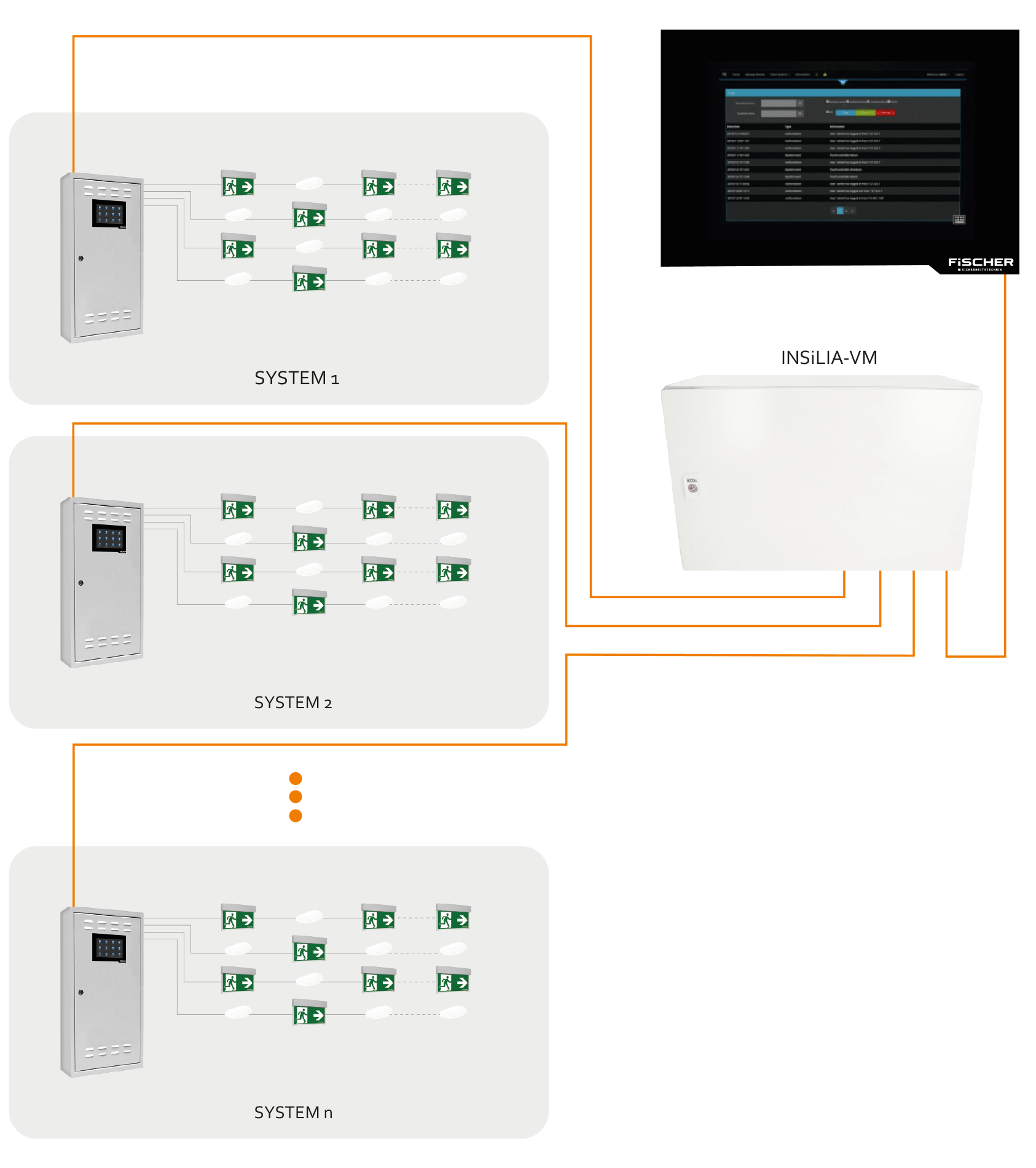
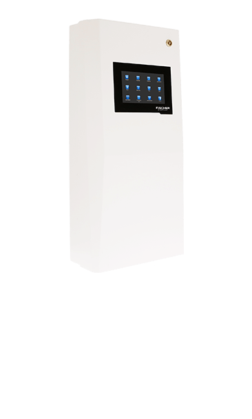
Smart Touch Controller
Used to control multiple INSiLIA LPS systems from a central location.
Requirements
»The INSiLIA systems to be monitored are in a separately formed network
» We recommend using the INSILIA-VM to ensure the supply even in the event of a power failure
Housing
» Material: metal
» Dimensions (HxWxD): 200 x 300 x 41 mm
» Protection: class II
» Degree of protection: IP20
Technical specifications
» 5,7” TFT Color – Touch – LCD
» RJ-45 Ethernet port
» Autonomy time in the event of a power failure
» Operating temperature +5 °C to +35 °C
Function
» Running function and battery tests
» Turn system on/off
» Checking status of individual systems
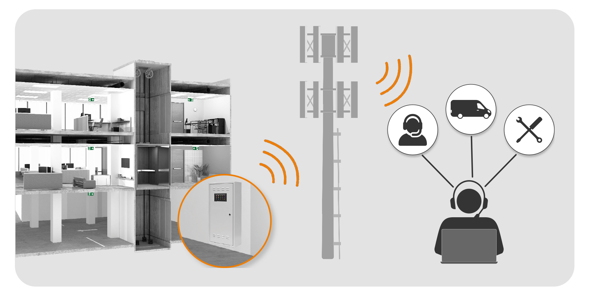
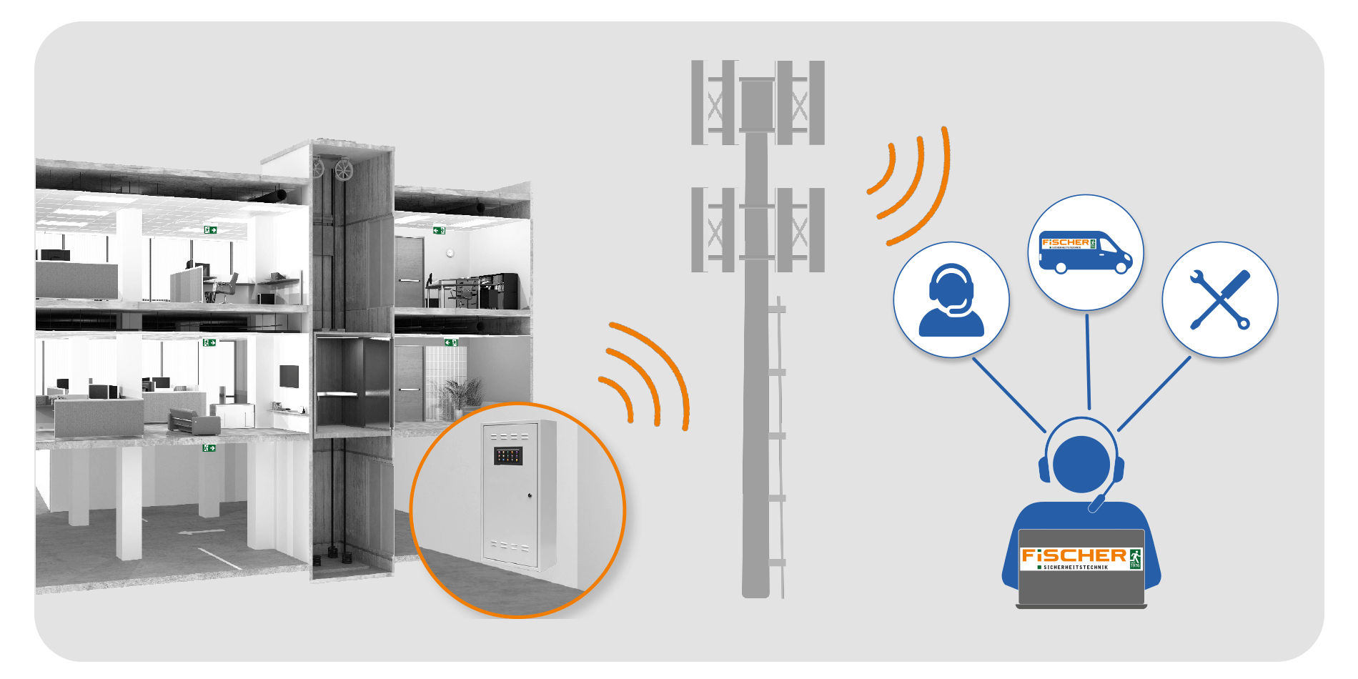
 -NCM
-NCM
With FiSCHER -NCM, the emergency lighting cloud monitoring, you can connect your INSiLIA2 to the FiSCHER data centre via the Internet of Things (IoT) using a mobile phone connection. Once connected to the data centre, you can access the status of the system from any location via an internet-capable end device with a web browser. In this way, you are immediately informed about the operating status and any fault messages. The use of-NCMis made possible by installing the optional FMS-NB-IOT-IN telecommunication system. In this way, you can either monitor systems in several properties yourself, or delegate the necessary tasks to us by means of a FiSCHER Maintenance Contract Plus. Daily on-site checks and are only required when necessary to optimise personnel costs and maximise operational safety.
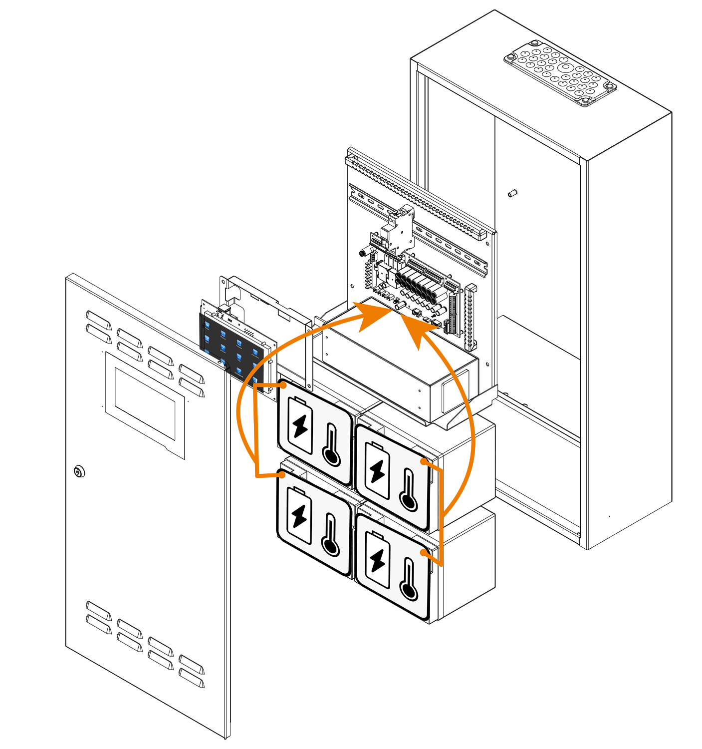
Integrated single battery monitoring
It is essential that batteries work reliably. If they do not, emergency lighting or the safety power supply fail to perform their duties in an emergency. Even if not yet required by standards, the monitoring of each individual battery block delivers valuable additional information to timely and appropriately respond to impending damage and failures. Therefore, the current draft of the European CENELEC Standard prEN 50171:2019 recommends battery monitoring systems that can monitor individual blocks.
The INSiLIA2 is delivered with an integrated single block monitoring already in the standard.
Function maintenance-E30
The functional integrity was verified by a type test at the independent Fire Protection Competence Center of the Materialprüfungsamt Universität Stuttgart.
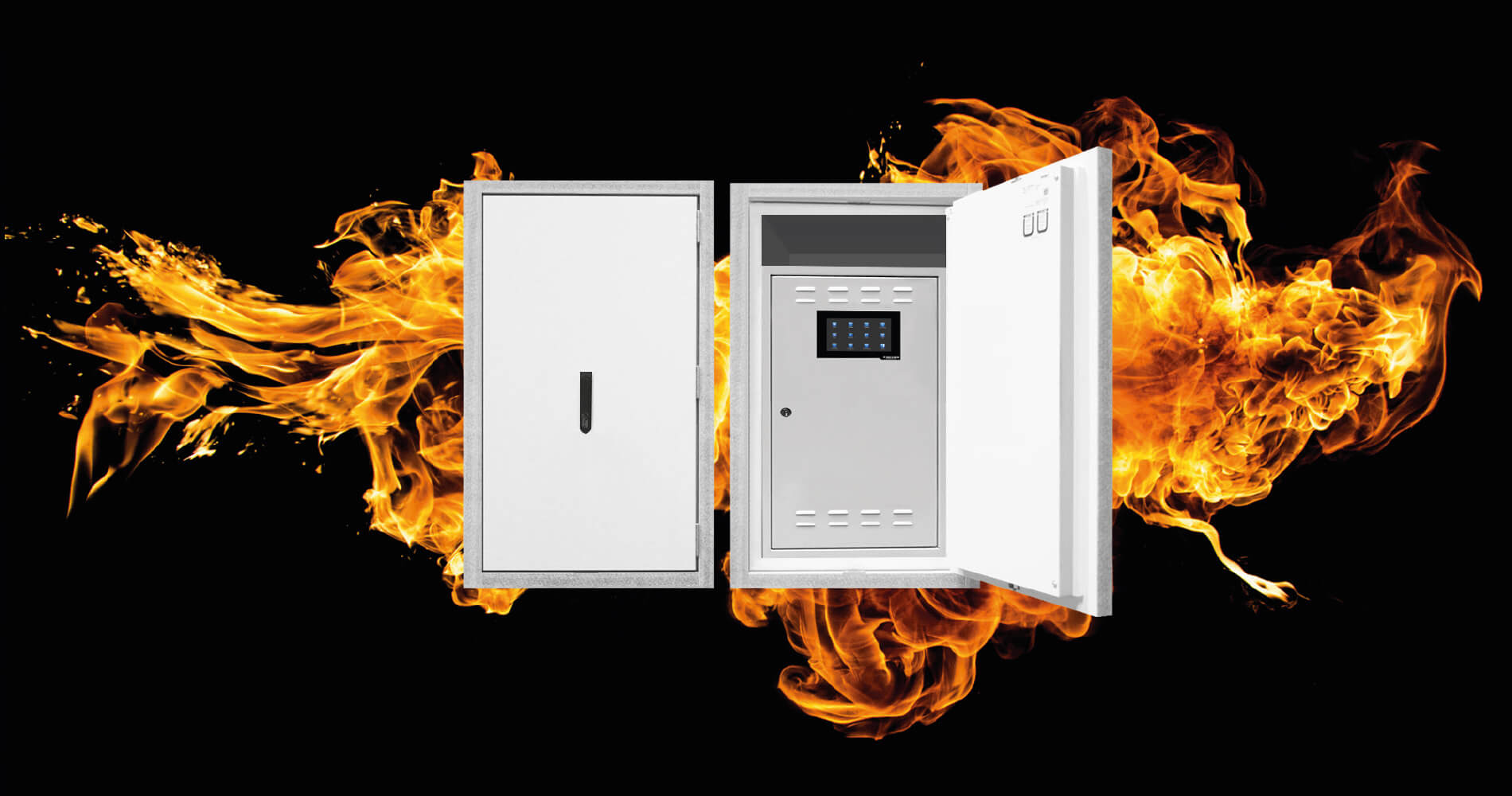
| Technical specifications | |||
| INSiLIA-40-8-E30 | INSiLIA-40-16-E30 | ||
| Dimensions (H x W x D mm): | 1219 x 669 x 425,5 | 12069 x 669 x 425,5 | |
| Weight (kg): | 79,5 | 312 | |
| Ambient temperature: | +5 °C up +30 °C | +5 °C up +30 °C | |
| Protection class: | II | II | |
| Degree of protection: | IP42 | IP42 | |
| IK-labelling: | IK10 | IK10 | |
| Fire resistance: | 30 min | 30 min | |
| Color: | Color white, similar to RAL 9010 | Color white, similar to RAL 9010 | |
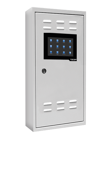
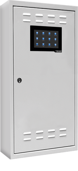
Systemvarianten
 |
|
 |
||
| Technical specifications | ||||
| INSiLIA2-7-4 Premium | INSiLIA2-12-4 Premium | INSiLIA2-12-4 | ||
| Dimensions (mm) | Height | 680 | 680 | 650 |
| Width | 330 | 330 | 350 | |
| Depth | 150 | 150 | 150 | |
| Battery nominal capacity | 7,2 Ah | 12 Ah | 12 Ah | |
| Battery life according to EURO BAT (@ 20 °C) |
5 years | 5 years | 5 years | |
| Number of final circuits | 4 | 4 | 4 | |
| Maximum connected load (W) | 1 h | 166 | 280 | 280 |
| 3 h | 64 | 110 | 110 | |
| 8 h | 25 | 46 | 46 | |
| Weight (kg) | 18,5 | 25,5 | 25,5 | |
| Supply voltage | 230 V AC 50/60 Hz ±10% or 216 V DC ±20% | |||
| Degree of protection | IP 20 | |||
| Protection class | I | |||
| Output voltage | 48 V DC ±20% | |||
| Max. Ø mains supply | 2,5 mm² | |||
| Max. Ø end circuit length | 2,5 mm² | |||
| Max. End circuit length | 500 m | |||
| Max. Power per end circuit | 120 W | |||
| Battery compartment in cabinet | yes | |||
| Single battery monitoring | temperature and voltage | |||
| Operating temperature | -5 °C up 30 °C | |||
 |
|
|
|
 |
||
| Technical specifications | ||||||
| INSiLIA2-18-4 | INSiLIA2-18-8 | INSiLIA2-33-8 | INSiLIA2-40-8 | INSiLIA2-40-16 | ||
| Dimensions (mm) | Height | 870 | 870 | 870 | 870 | 1500 |
| Width | 460 | 460 | 460 | 460 | 490 | |
| Depth | 220 | 220 | 220 | 220 | 280 | |
| Battery nominal capacity | 18 Ah | 18 Ah | 33 Ah | 40 Ah | 40 Ah | |
| Battery life according to EURO BAT (@ 20 °C) |
5 Jahre | 5 Jahre | 10 Jahre | 10 Jahre | 10 Jahre | |
| Number of final circuits | 4 | 8 | 8 | 8 | 16 | |
| Maximum connected load (W) | 1 h | 8 | 423 | 734 | 890 | 2 x 890 |
| 3 h | 168 | 168 | 309 | 375 | 2 x 375 | |
| 8 h | 72 | 72 | 137 | 167 | 2 x 167 | |
| Weight (kg) | 45,0 | 45,0 | 60,0 | 72,5 | 14,5 | |
| Supply voltage | 230 V AC 50/60 Hz ±10% or 216 V DC ±20% | |||||
| Degree of protection | IP 20 | |||||
| Protection class | I | |||||
| Output voltage | 48 V DC ±20% | |||||
| Max. Ø mains supply | 2,5 mm² | |||||
| Max. Ø end circuit length | 2,5 mm² | |||||
| Max. End circuit length | 500 m | |||||
| Max. Power per end circuit | 120 W | |||||
| Battery compartment in cabinet | yes | |||||
| Single battery monitoring | temperature and voltage | |||||
| Operating temperature | -5 °C up 30 °C | |||||

-
PARTNERS


-

-
Social commitment


-