ZBX Device
/ Overview / Central Power System (CPS) / ZBX / Device
/ Overview / Central Power System (CPS) / ZBX / Device
ZBX
CENTRAL BATTERY SYSTEMS (CBS) FOR OBJECTS OF ALL SIZES
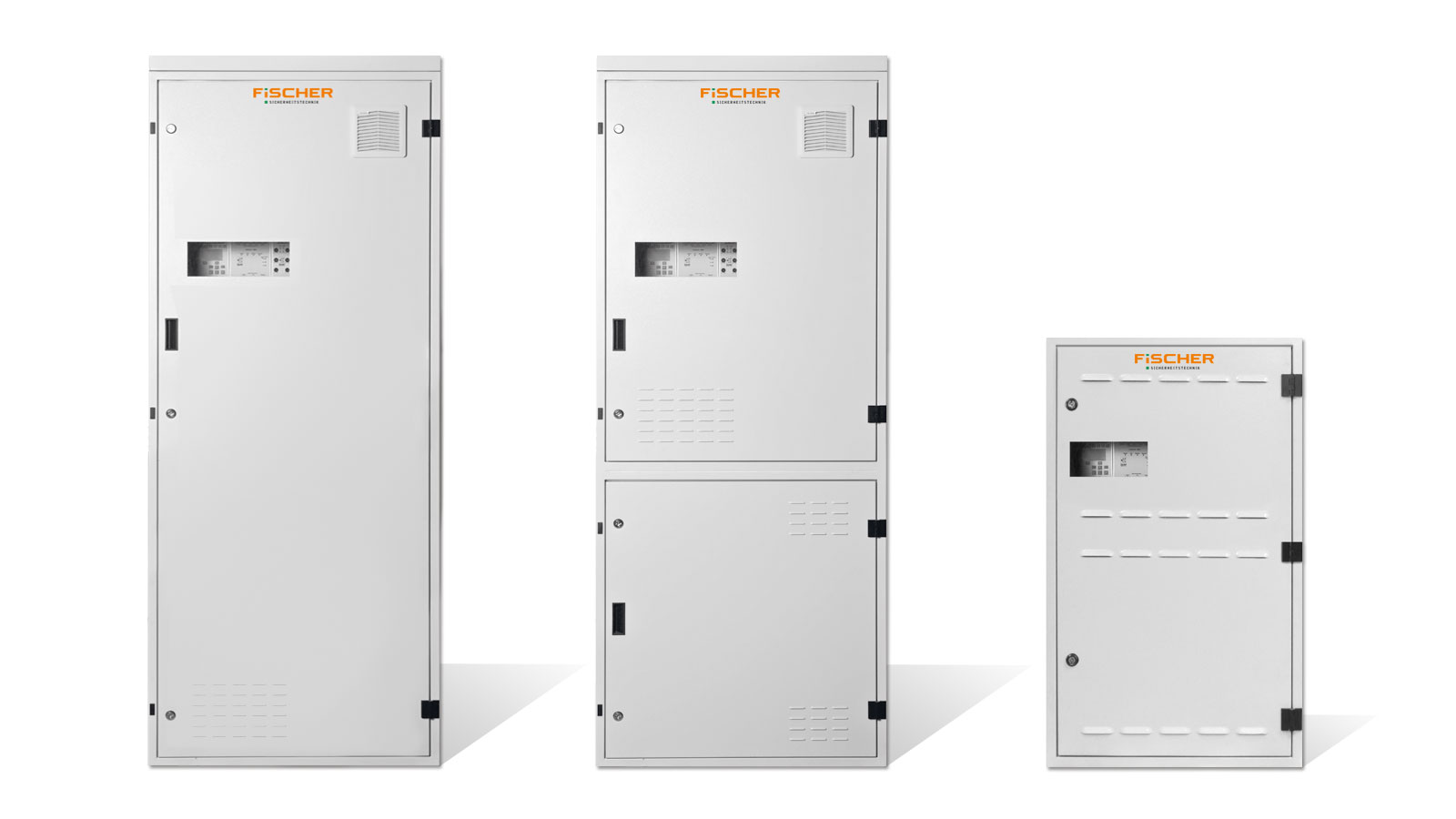
ZBX-S / ZBX-C / ZBX-M
-
- Common operation of 20 luminaires as for maintained (M) or non maintained (NM) within one circuit – for luminaires with ADS module
- Each connected luminaire can be configured independently (M/NM)
- Area by area (groups) assignment for monitoring the critical circle
- Single or combined switching of luminaires via switching inputs from the CBS
- Individual luminaire monitoring via the supply line with the ADS or ADL module (no separate bus line necessary) in standard
- Automatic function test
-
-
- Automatic searching and adding of emergency lighting luminaires
- Remote switch-off
- Programming, monitoring and visualization of the entire system via software (optional)
- iCCIF for monitoring the critical circuit
- 4 potential-free relay outputs 24 V / 0.5 A for transmitting switching signals to the building management system
- Integrated ZBX-LS-230 switch monitoring module with 8 inputs 230 V AC
- Wire labelling on all internal lines
-
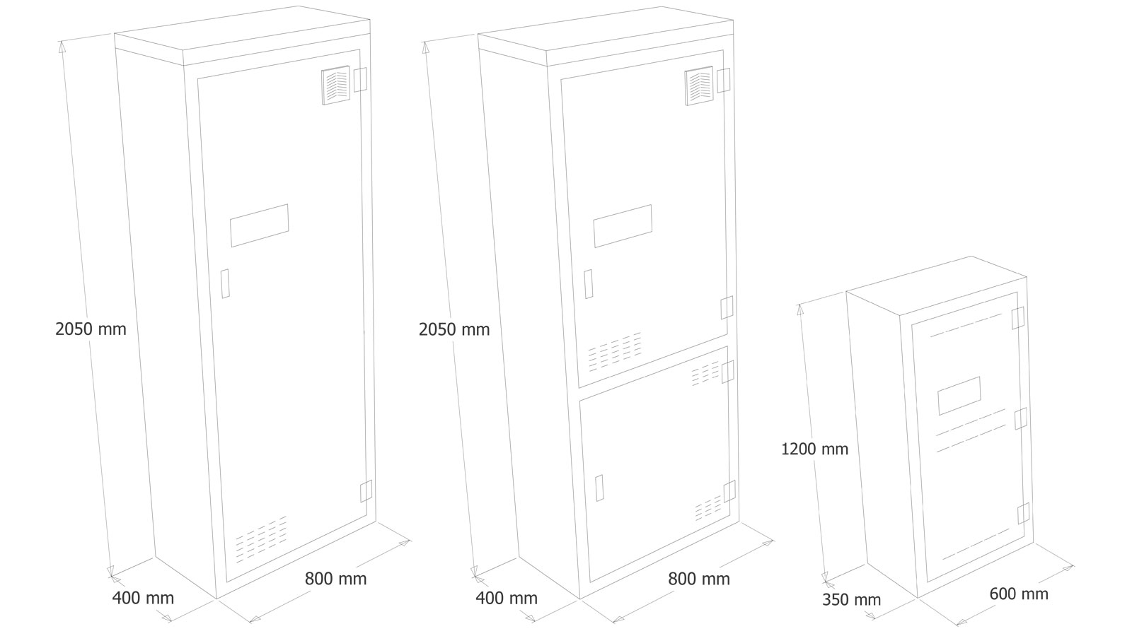
DIMENSIONS
ZBX-S
- Degree of protection: IP21
- Protection class: I
- Colour: RAL7035 (light grey)
- Dimensions: 2050 x 800 x 400 mm (HxWxD)
- Optimum operating temperature: 0°C – 25°C*.
- Nominal operating time: 1 h, 3 h or 8 h
- Connected load: max. 5.5 kW DC
- Prepared for: 60 final circuits
ZBX-C
- Combination cabinet with battery compartment
- Degree of protection: IP 21
- Protection class: I
- Colour: RAL7035 (light grey)
- Dimensions: 2050 x 800 x 400 mm (HxWxD)
- Optimum operating temperature: 0°C – 25°C *
- Nominal operating time: 1 h, 3 h or 8 h
- Connected load: max. 5.5 kW DC
- Prepared for: 40 final circuits
ZBX-M
- Combination cabinet with battery compartment
- Degree of protection: IP 21
- Protection class: I
- Colour: RAL7035 (light grey)
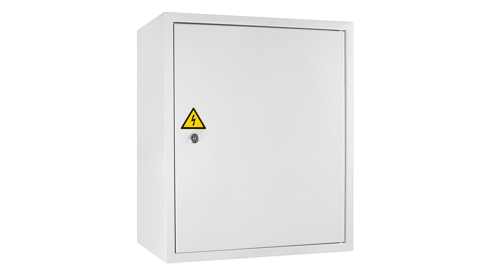
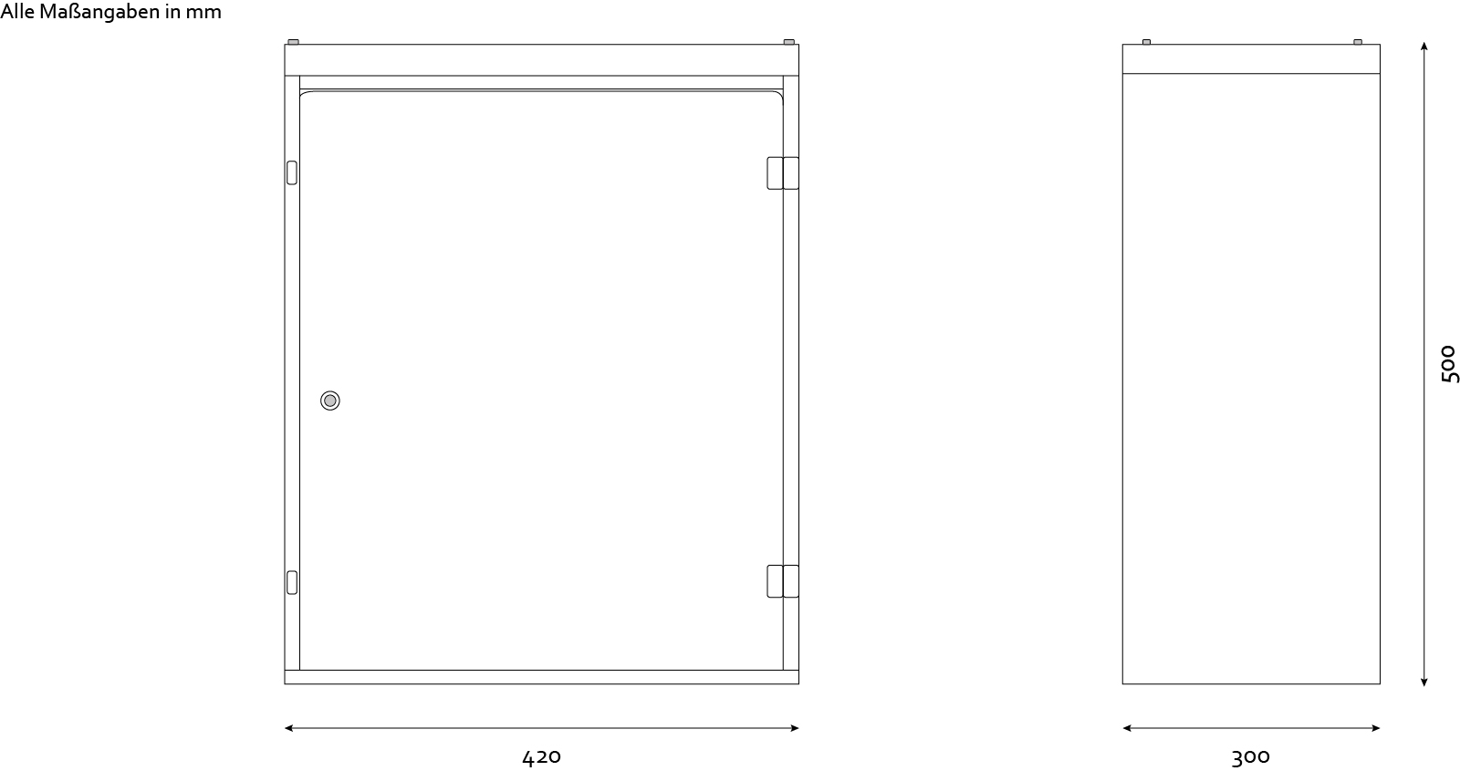
- Dimensions: 1200 x 600 x 350 mm (HxWxD)
- Optimum operating temperature: 0°C – 25°C *
- Nominal operating time: 1 h, 3 h or 8 h
- Connected load: max. 1.8 kW DC
- Prepared for: 16 final circuits
* strong deviations can lead to a reduced lifetime
WIRING DIAGRAM
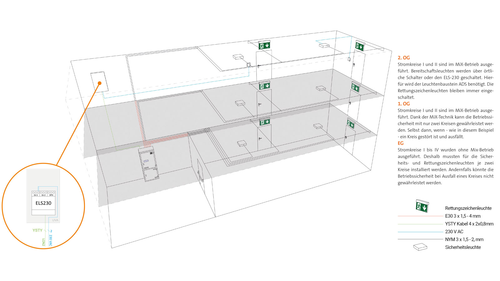
MIX TECHNOLOGY VS. CONVENTIONAL INSTALLATION

ADVANTAGES OF THE MIX TECHNOLOGY:
Operation of the luminaires in different operating modes (M, NM and switched) within one circuit
Further advantages:
- shorter cable lengths
- less circles necessary
- lower installation effort
- operating mode can be changed afterwards without rewiring
CONVENTIONAL INSTALLATION
A conventional installation differs from MiX technology in essential aspects:
- only one operating mode per circuit possible
- more circles necessary
- higher installation effort
- high costs for future changes
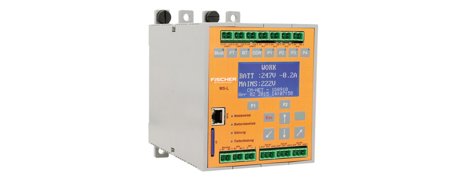
CENTRAL PROCESSING UNIT (CPU)
MS-L
- 4 function keys
– Block
– Start function test
– Start battery test
– Resetting of deep discharge errors - 4 potential-free 24V inputs, freely programmable, for e.g: function test, battery test, sensor input etc.
- 4 function keys for free programming
– Switching on the circuits via AC
– Switching on the circuits via DC
– Resetting various alarms
– Functional test without preheating phase - 3 x LON-BUS
- 2 timers
- Connection for iCCIF to monitor the critical circuit
- Remote shutdown
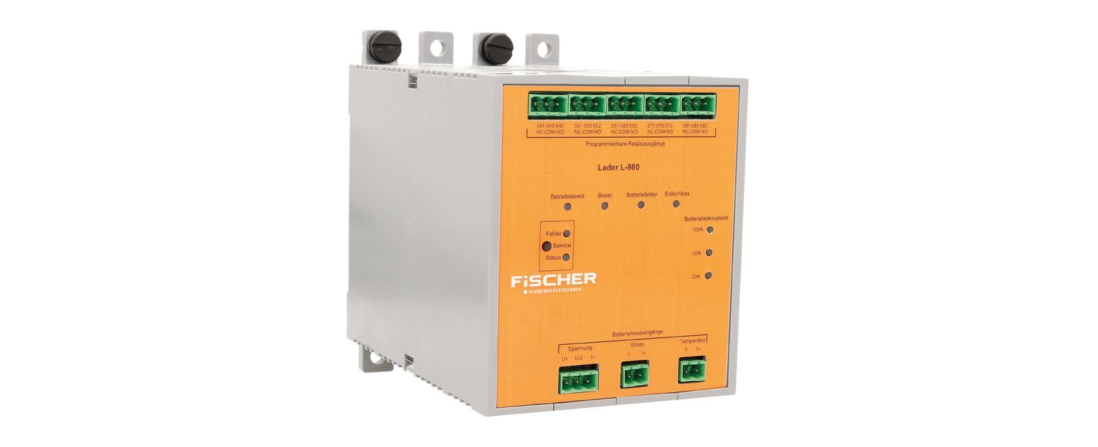
CHARGING DEVICE L-980
FEATURES
- Earth fault monitoring
- Deep discharge protection
- Battery symmetry monitoring
- Fan contact
- 3 connections for
– Charge voltage monitoring
– Charge current monitoring
– Temperature monitoring
TECHNICAL SPECIFICATIONS
- High charge: max. 265 V DC
- Preset float charge: 245.1 V DC
- Charging power: 980 W
- Charging current: 4.5 A
- Deep discharge protection: 183.6 V DC
- Outputs: 4 programmable relay outputs 24V/0.5A
CONNECTIONS
- Connection for passing on the charging status
- 4 potential-free outputs, freely programmable
- Passing on the battery state of charge
- Quick access button
SWITCH MONITORING MODULE
FEATURES
- Monitoring of light switches
- Programmable and reversible logic operations for the inputs
- Option of monitoring individual general lighting circuits
- Adjustable switch back time
- Quick access button
- Quick access button
- LED status display for inputs
TECHNICAL SPECIFICATIONS
- 8 potential-free inputs (230 V AC), switch-back time adjustable between 1 min and 1 h
- Operational logic of the inputs can be reversed
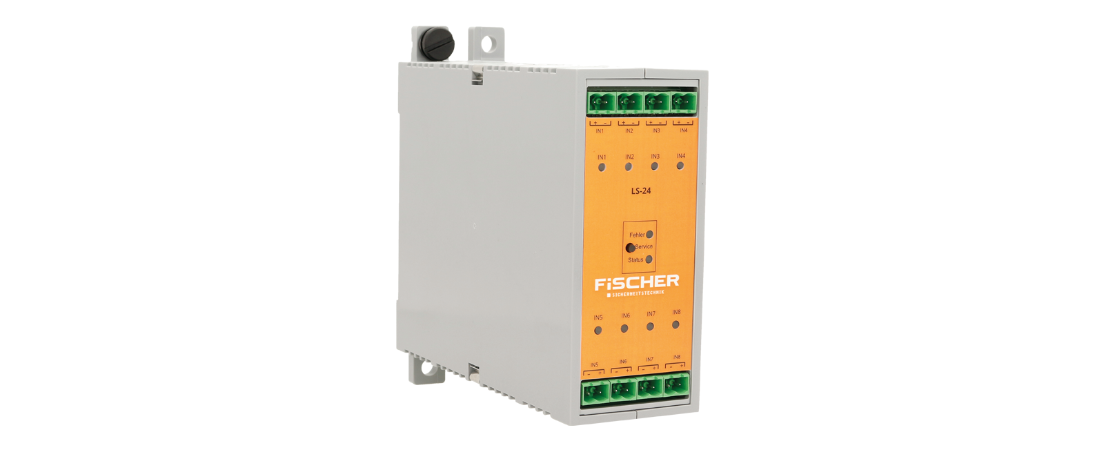
LS-24
FEATURES
- Monitoring of a 24 V DC closed-circuit current loop
- Processing of switching commands from the building management system via potential-free inputs
- Adjustable switch back time
- Quick access button
- LED status display for module status
- LED status display for input status
TECHNICAL SPECIFICATIONS
- 8 closed current loops 24V, switch-back time adjustable between 1 min and 1 h
POWER CIRCUIT MODULES
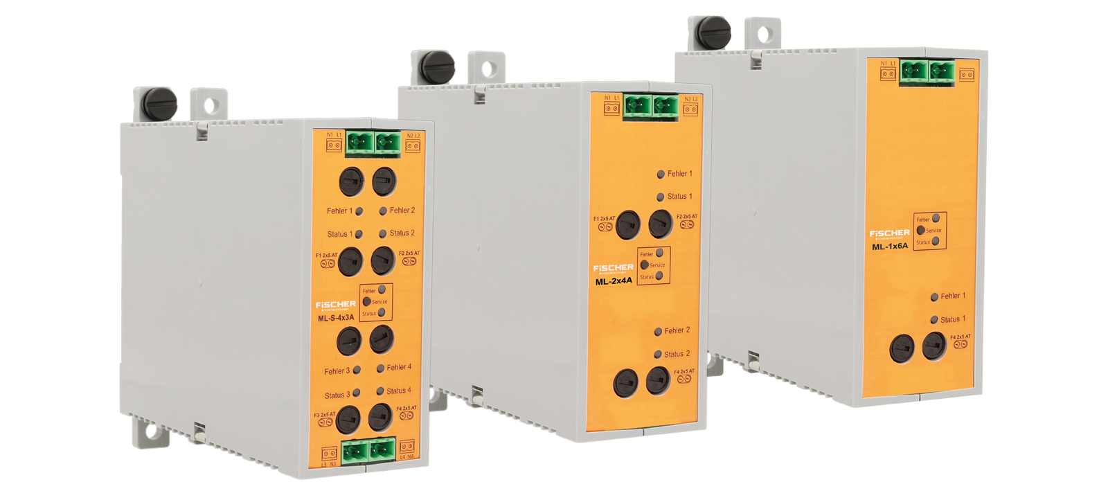
MLS-4x3A
- Number of circles: 4
- Current per circuit: 3 A
- Fuse protection: 5 AT / 250 V
- MIX technology: Yes
MLS-2x4A
- Number of circles: 2
- Current per circuit: 4 A
- Fuse protection: 6.3 AT / 250 V
- MIX technology: Yes
MLS-1x6A
- Number of circles: 1
- Current per circuit: 6 A
- Fuse protection: 10 AT / 250 V
- MIX technology: No
BUS REMOTE CONTROL PANEL
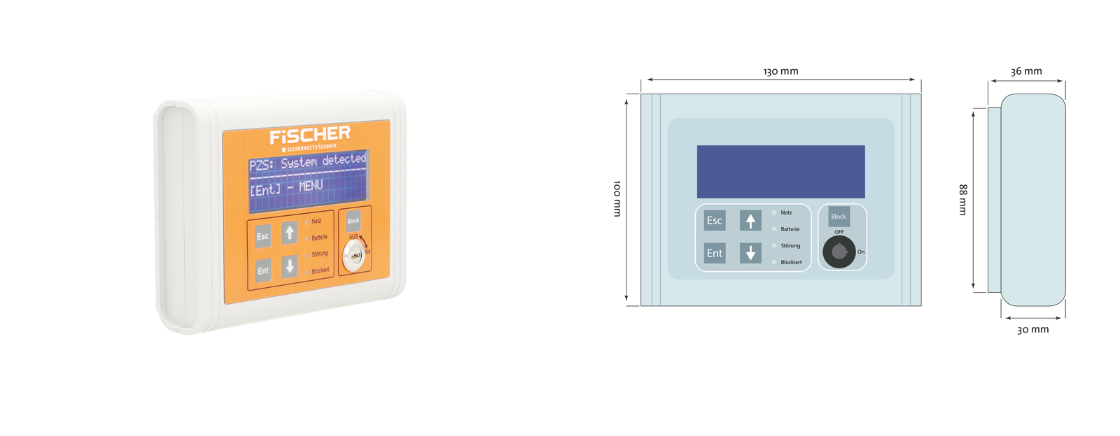
ZBX-FMS
- System status displayed in plain text
- Optical status indication via LED and LCD
- Acoustic warning in case of faults
- BUS connection to the device via CAT 6 or higher
- In compliance with DIN VDE 0100 part 718 – NHX cable not required
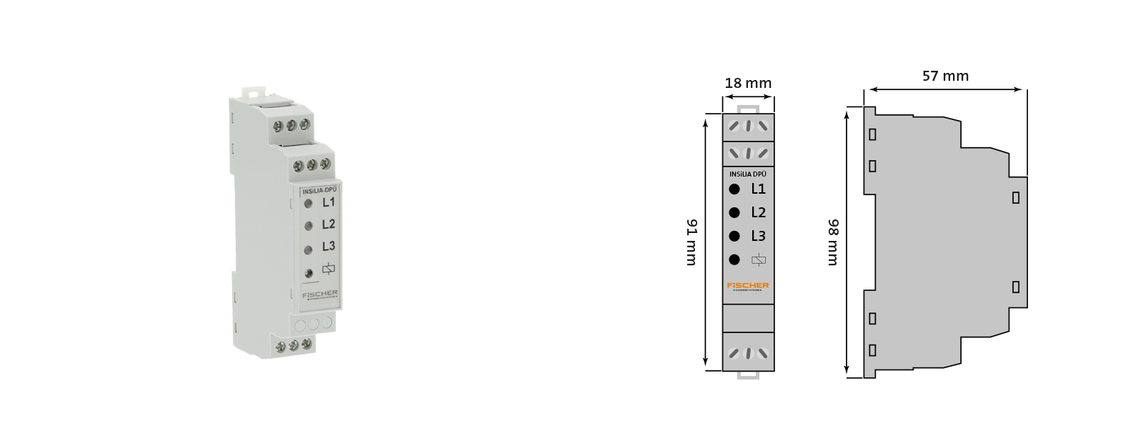
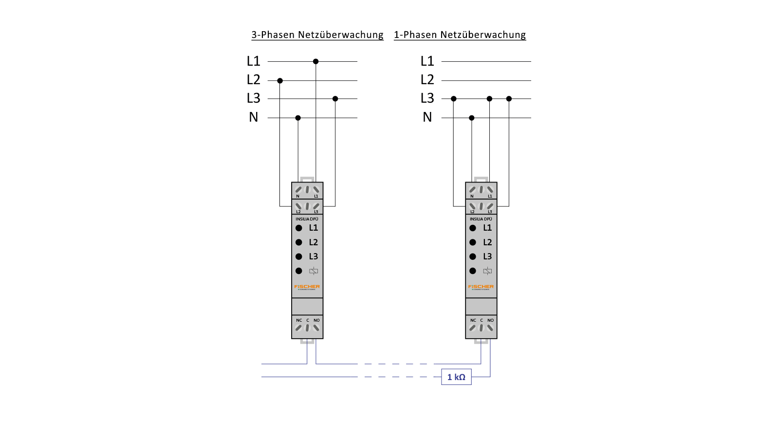
Insilia DPÜ
UNDERVOLTAGE MONITOR
- With ICCIF loop monitoring
- No NHX line necessary
- Restores the condition according to DIN VDE 0100 part 718 section 718.563.8 in case of power failure
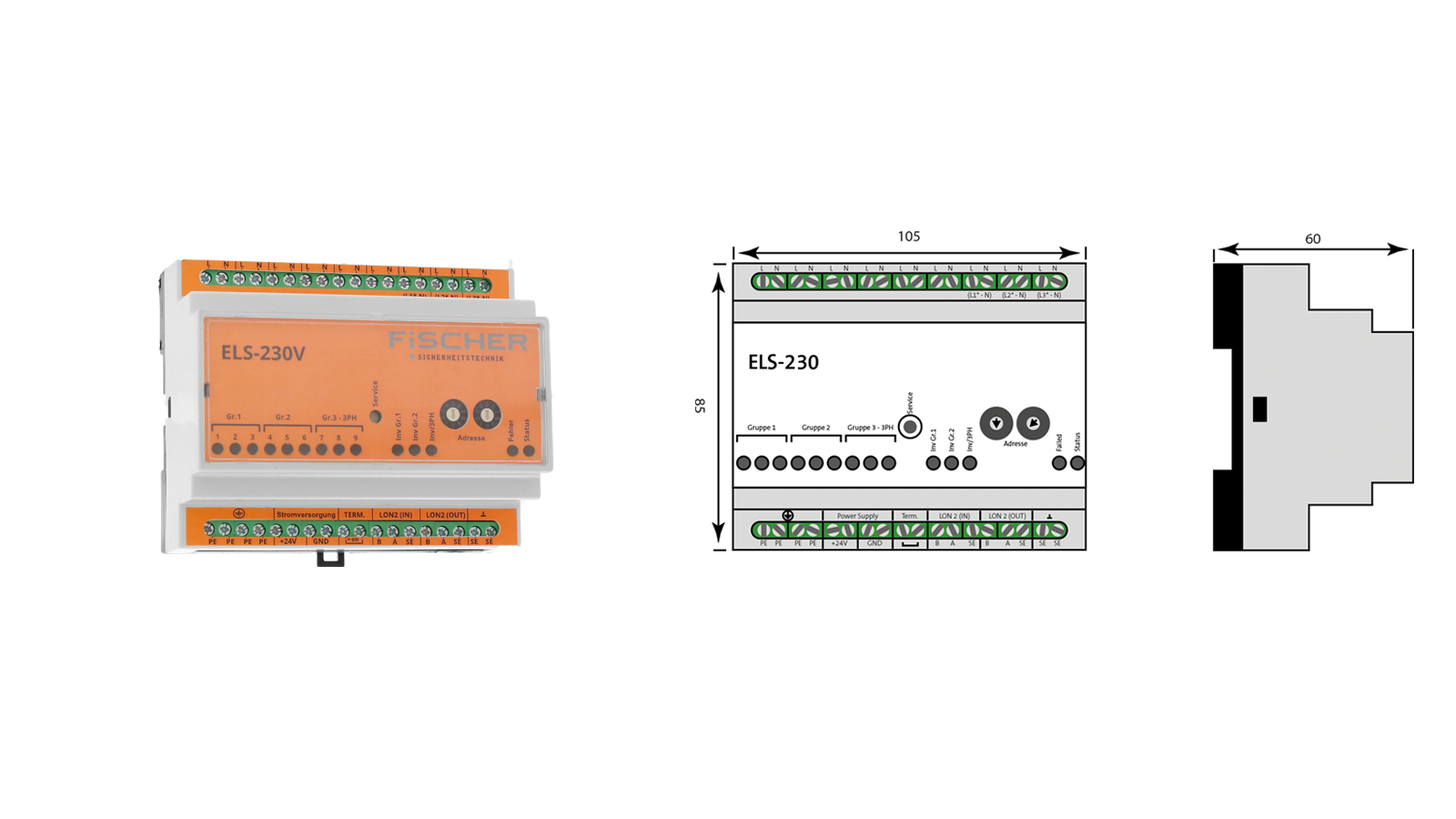
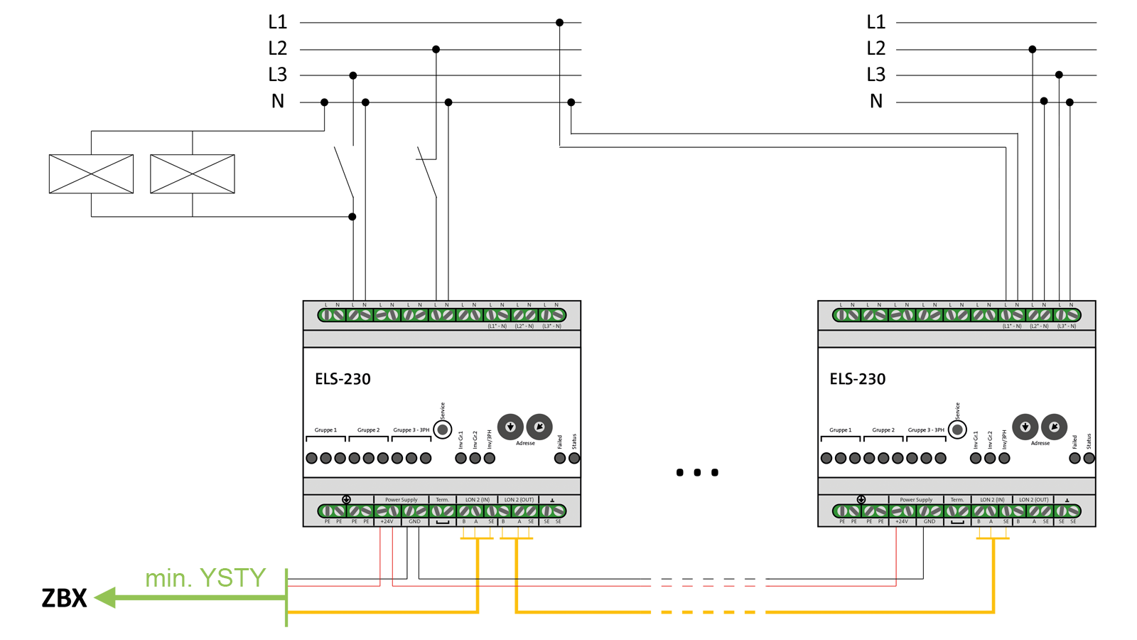
EXTERNAL SWITCH REQUEST MODULE
FEATURES
- Switch monitoring of the general lighting
- Phase monitoring function
- Programmable and reversible circuit logic for input groups
- Monitoring of individual fuses
- Adjustable switch back time
- Quick access button
- LED status indication for module status
- LED status indication for inputs
TECHNICAL SPECIFICATIONS
- Supply voltage 24 V DC
- Protection class: I
- Degree of protection: IP21
- Operating temperature -10°C to +40°C
- 9 potential-free, separate inputs
- 3 input groups with 3 inputs each
- Phase monitoring function via input 7 – 9 (group 3)
- Switch-back time adjustable between 1 min and 1 h
- LON-BUS
- BUS address range 1 – 30
- Dimensions 105 x 85 x 60 (W x H x D)
- 2.5 mm² connection terminals
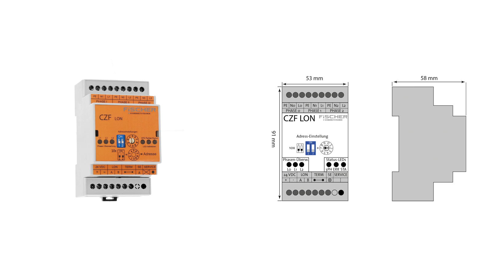
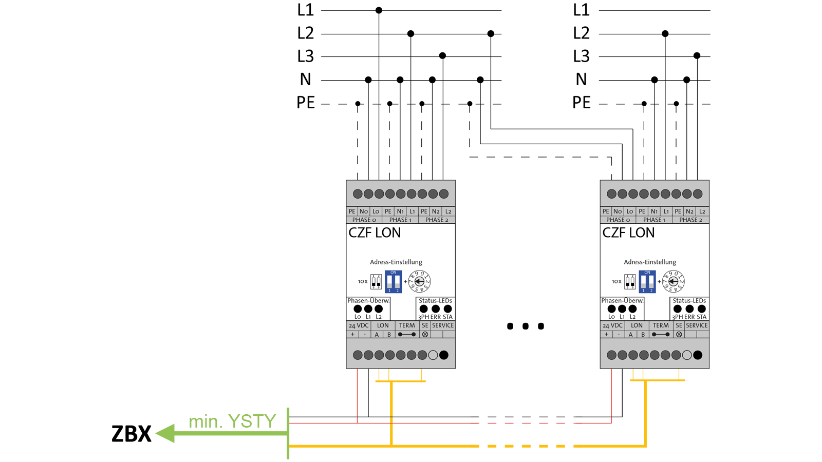
BUS NETWORK GUARD
BENEFITS
- No need to use an NHX cable
- Tracing of the location in the event of a power failure for a faster location of the fault
- Suitable for 1- or 3-phase operation
- Outer conductor of different circles can be measured with a network monitor
- Compact design, top-hat (DIN)Rail mounting
- Individual circuits can be assigned to each CZF-LON – this enables the emergency lighting to be switched on in certain areas
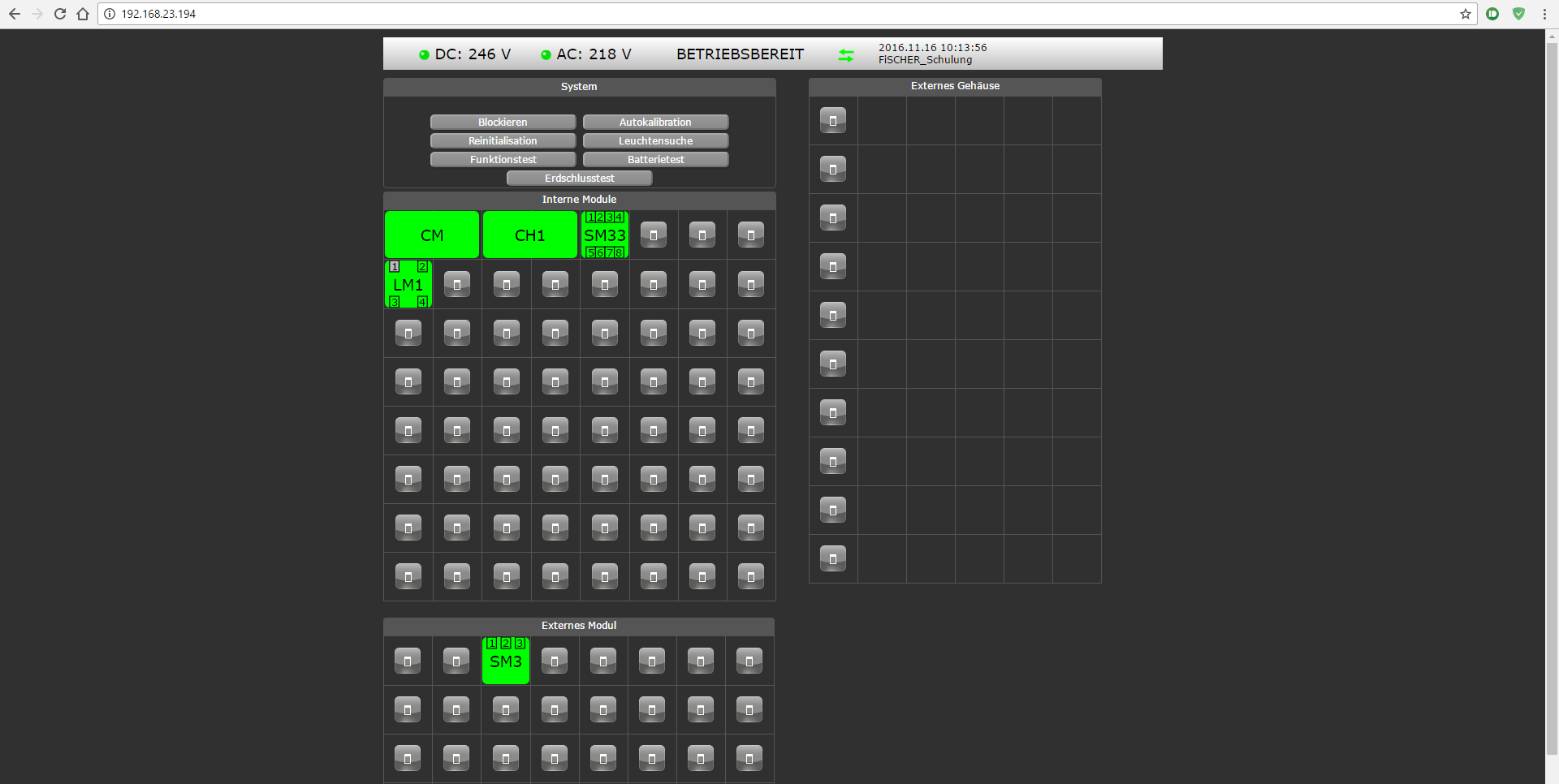
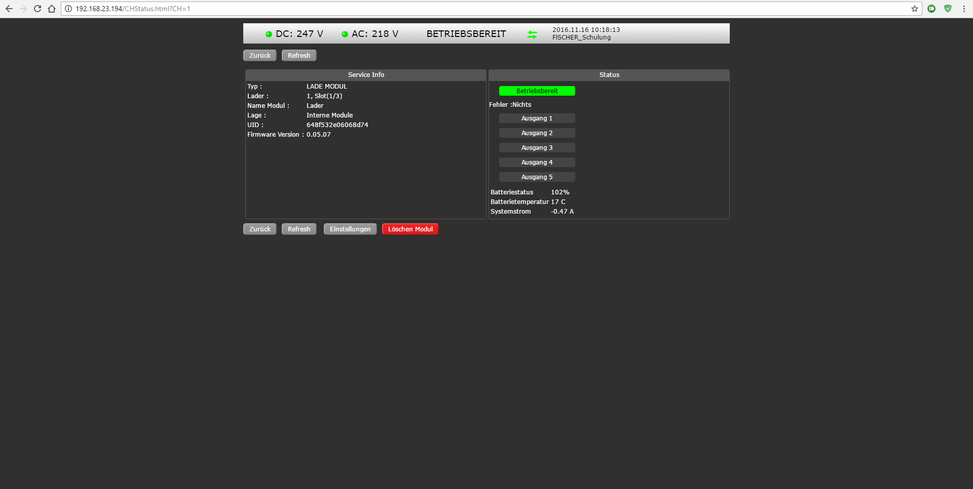
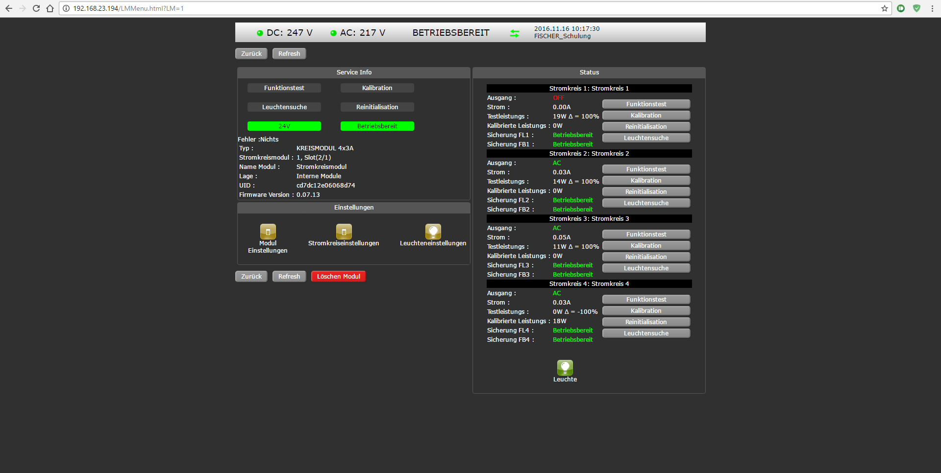
Web-Interface
Main
Lader
Leuchtenmodul
ZBX-US
ZBX-Unterstationen
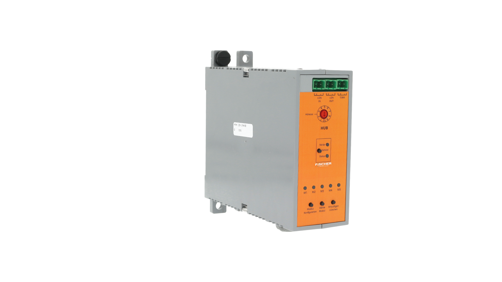
ZBX MODULE
- Prepared for bus through-wiring
- Prepared for bus through-wiring
- Integrated resistor for bus termination
- Easy installation of the expansion modules via control buttons
- Control LED for quick status control of the expansion modules
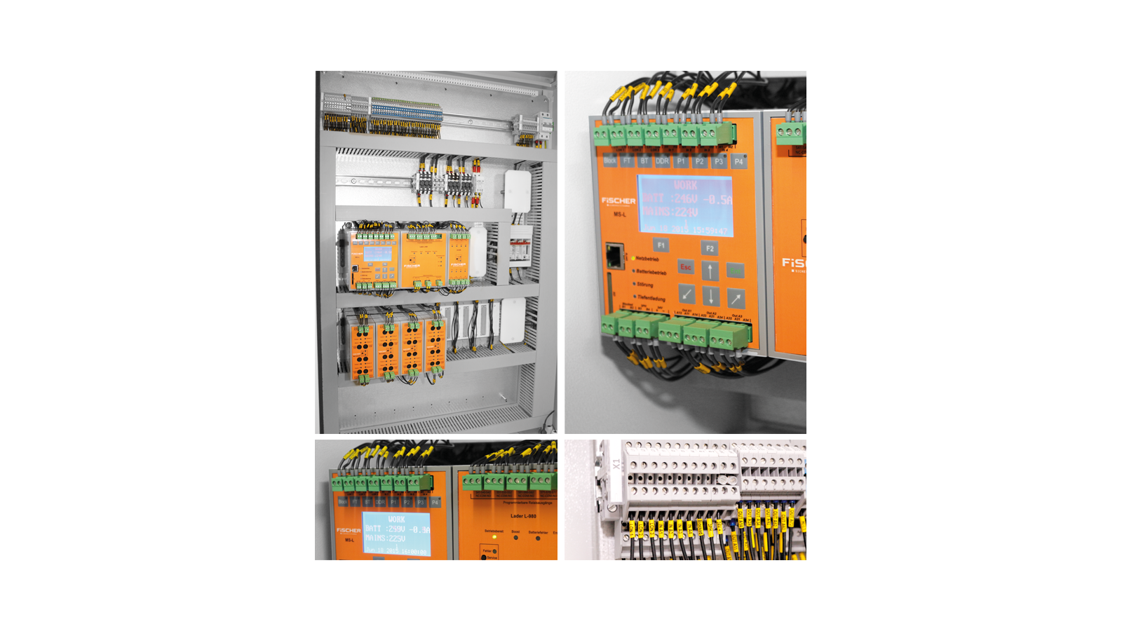
DETAIL PICTURES
Downloads
-

-
Company headquarters
FiSCHER Akkumulatorentechnik GmbH
Im Taubental 41
41468 Neuss
Germany -
Phone & Email
Switchboard: +49 2131 52310-0
Technical Support: +49 2131 52310-89
Purchase advice and order processing for luminaires and accessories:
Tel: +49 2131 52310-21
Fax: +49 2131 52310-40
Further contact options
E-Mail: info@akkufischer.de -
You can find us here
FiSCHER Akkumulatorentechnik GmbH
Privacy policy -
Imprint -
General terms and conditions -
Warranty conditions -
maintenance contract terms -
REACH Declaration -
Sitemap





 ZBX-Broschüre
 GAEB ZBX_C-16