
CENTRAL BATTERY SYSTEMS FOR OBJECTS OF ALL SIZES
WHAT MAKES THE ZB2 SERIES SPECIAL
The basic functionality of central power supplies for emergency and safety lighting has changed little for years. With the new ZB2 series, we maintain the familiar standards, but for the first time offer a combination of new, digital innovations that significantly improve handling and functionality.
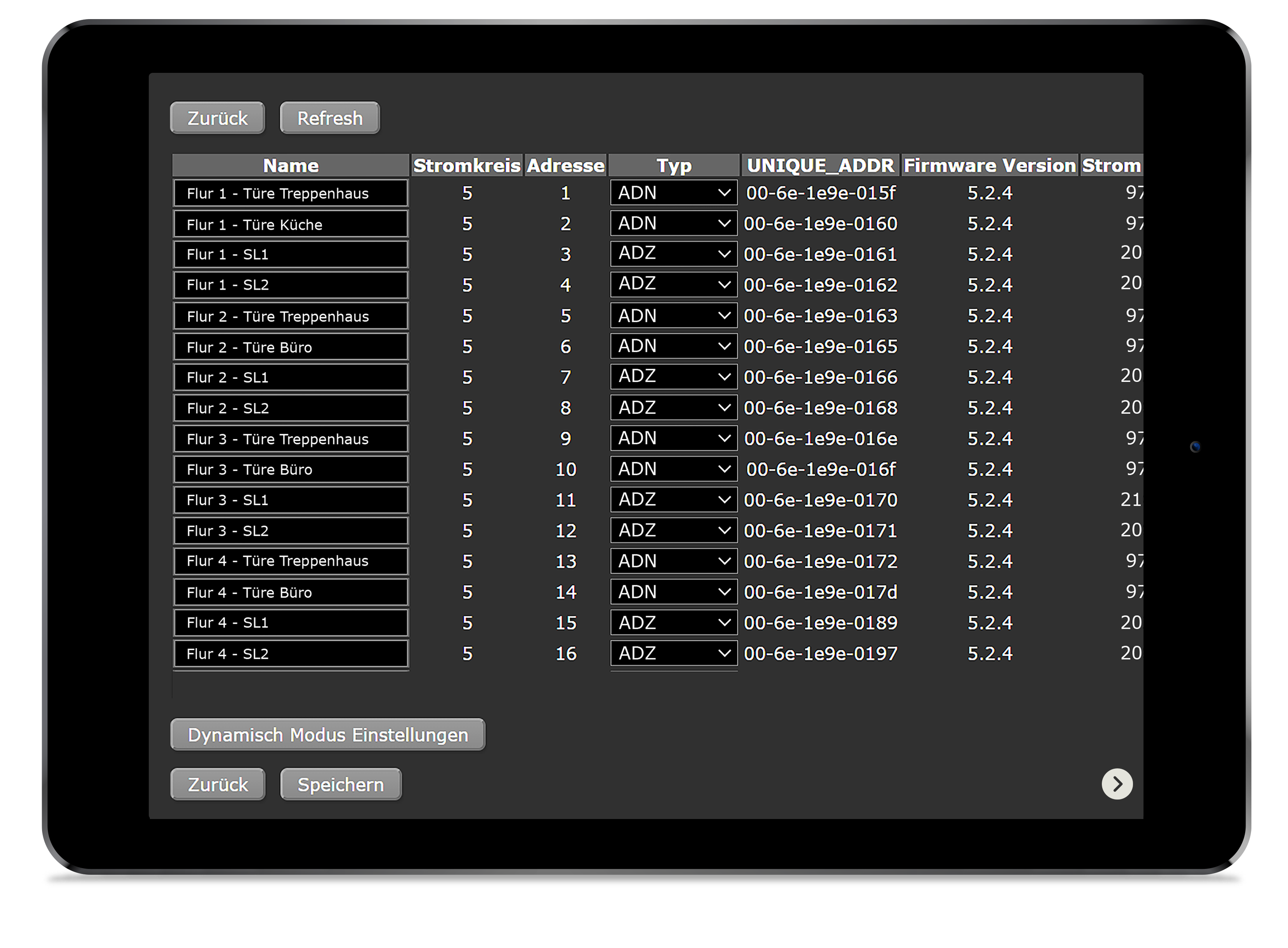
UNIQUE – ADDRESS MODULES
- UNIQUE addresses for quick assignment of luminaires
- no incorrect programming of double addresses
- sticker for building plans enclosed
- different operating modes (continuous light, standby light, switched standby light) in one final circuit
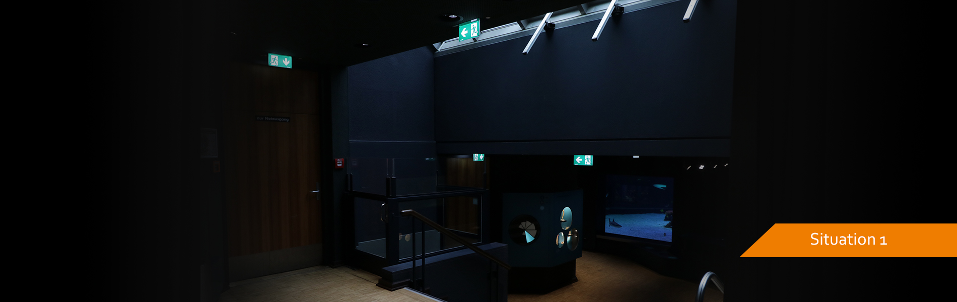
- switchable brightness levels (module-dependent) for cinema, auditorium or night watchman setup
 -NCM
-NCM
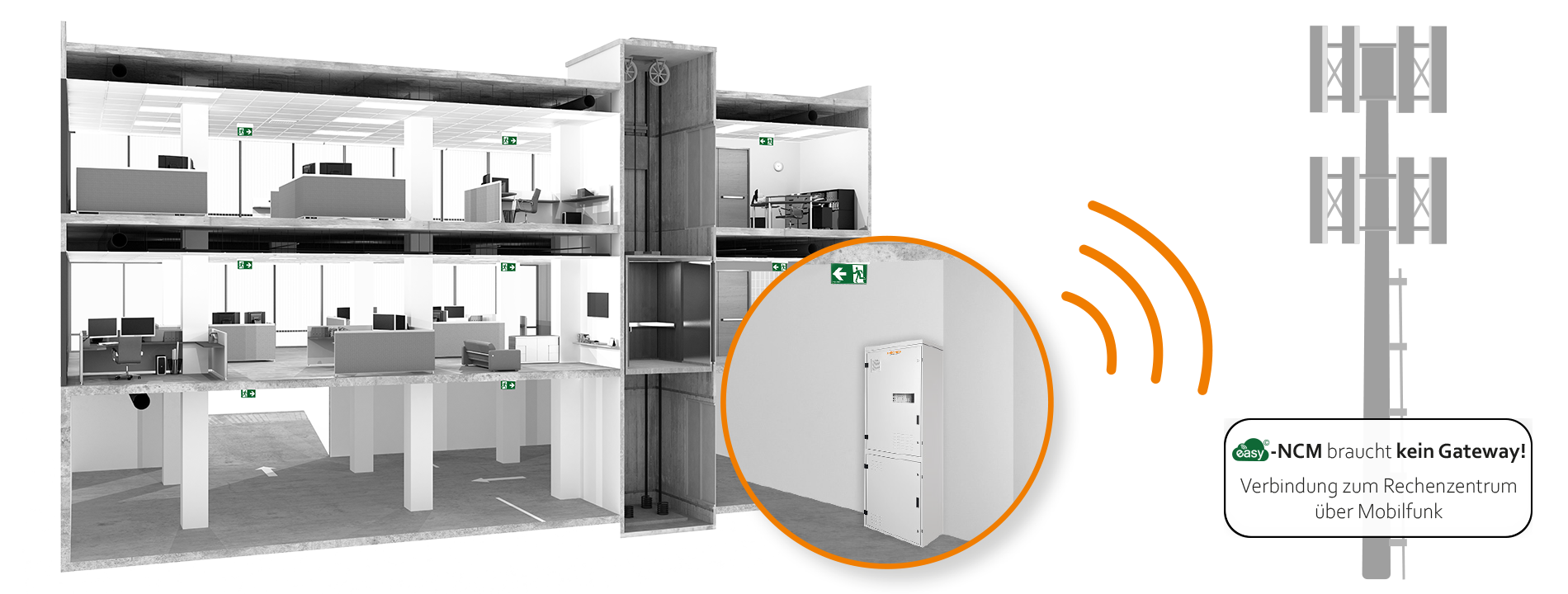


ADVANCED NETWORKING
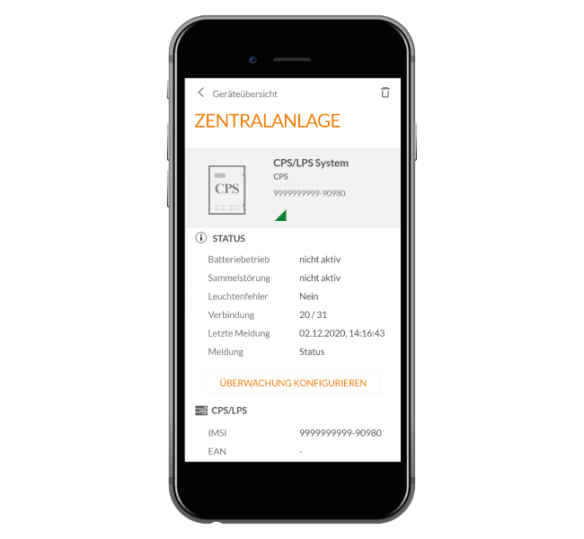
The systems of the ZB2 series offer full network capability without additional costs. An extended connection to the building management system is possible at any time.
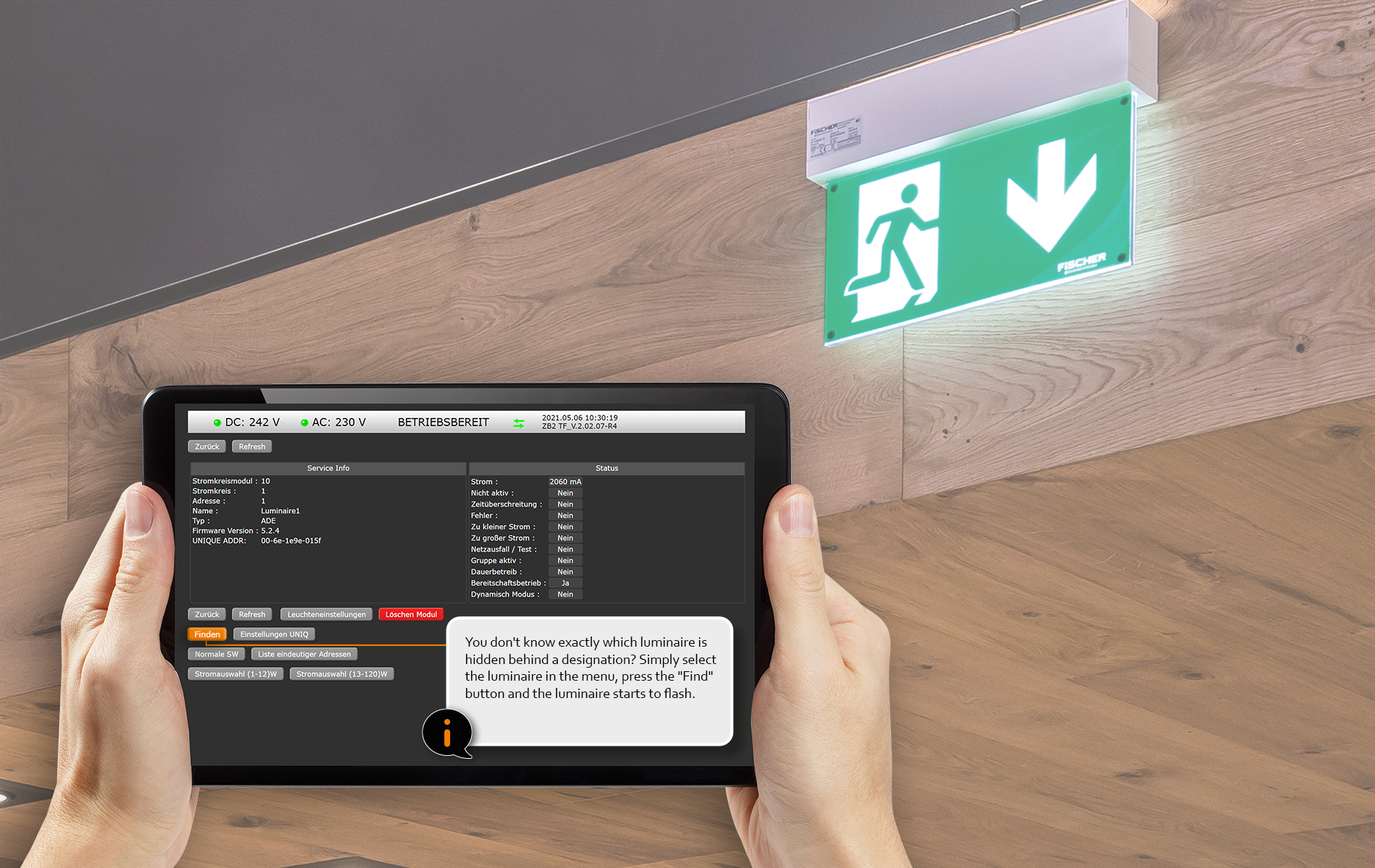
- The password-protected web interface simplifies operation and can be used to program the system.
- Full support of the BACnet protocol down to the details of each individual luminaire. The documentation of the parameters can be provided by your BACnet partner.
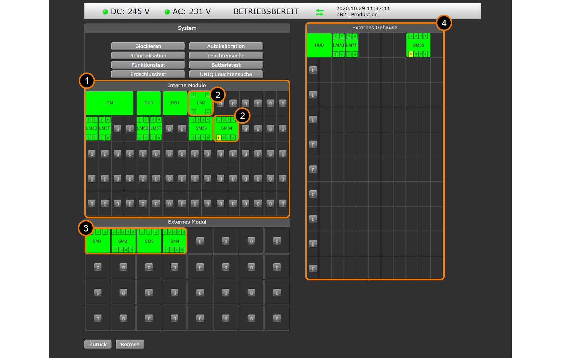
- Schematic representation of the emergency lighting system including any sub-distributions.
- Regular e-mail dispatch of status reports or direct e-mail notification for defined events can be programmed.
- Direct and detailed access to all modules and their settings
- Password level protected access to the complete programming of the system.
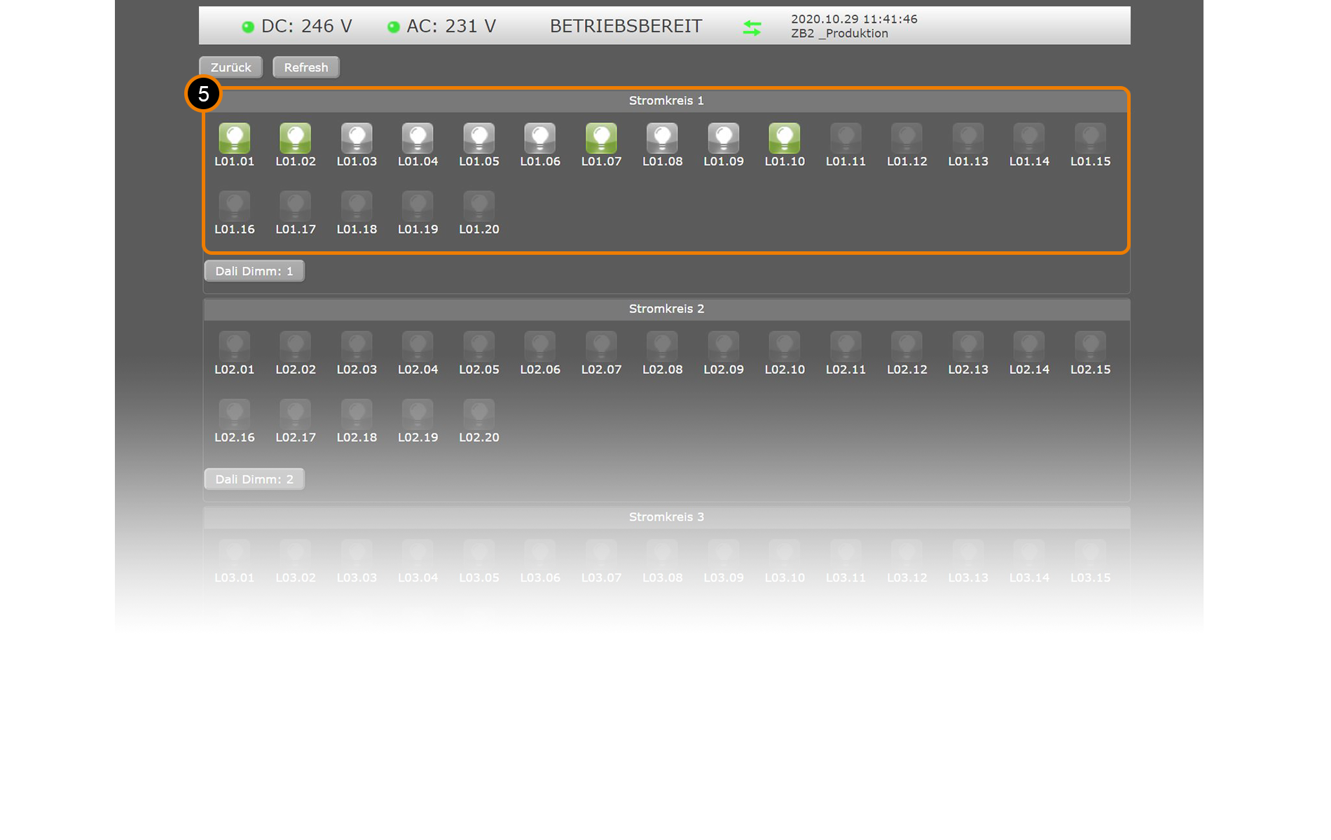
- Graphic overview of the final circuits including the status of the lights.
- Easily back up the configuration of the system and luminaires as well as the event log
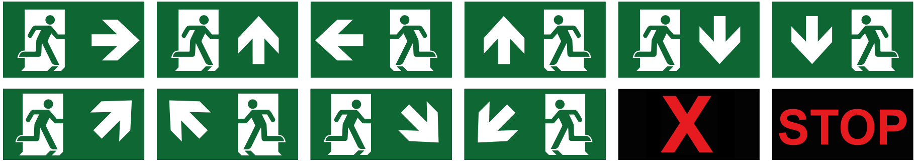
DYNAMIC ESCAPE ROUTE GUIDANCE
Overview of pictograms that can be displayed:


WIRING DIAGRAM
Overview of a classic ZB2 installation in several fire compartments and a sub-distribution for the emergency lighting in a neighboring building. The supply of the general lighting is monitored by a bus network monitor CZF-LON. The status of the entire emergency lighting system can be called up via a web application.
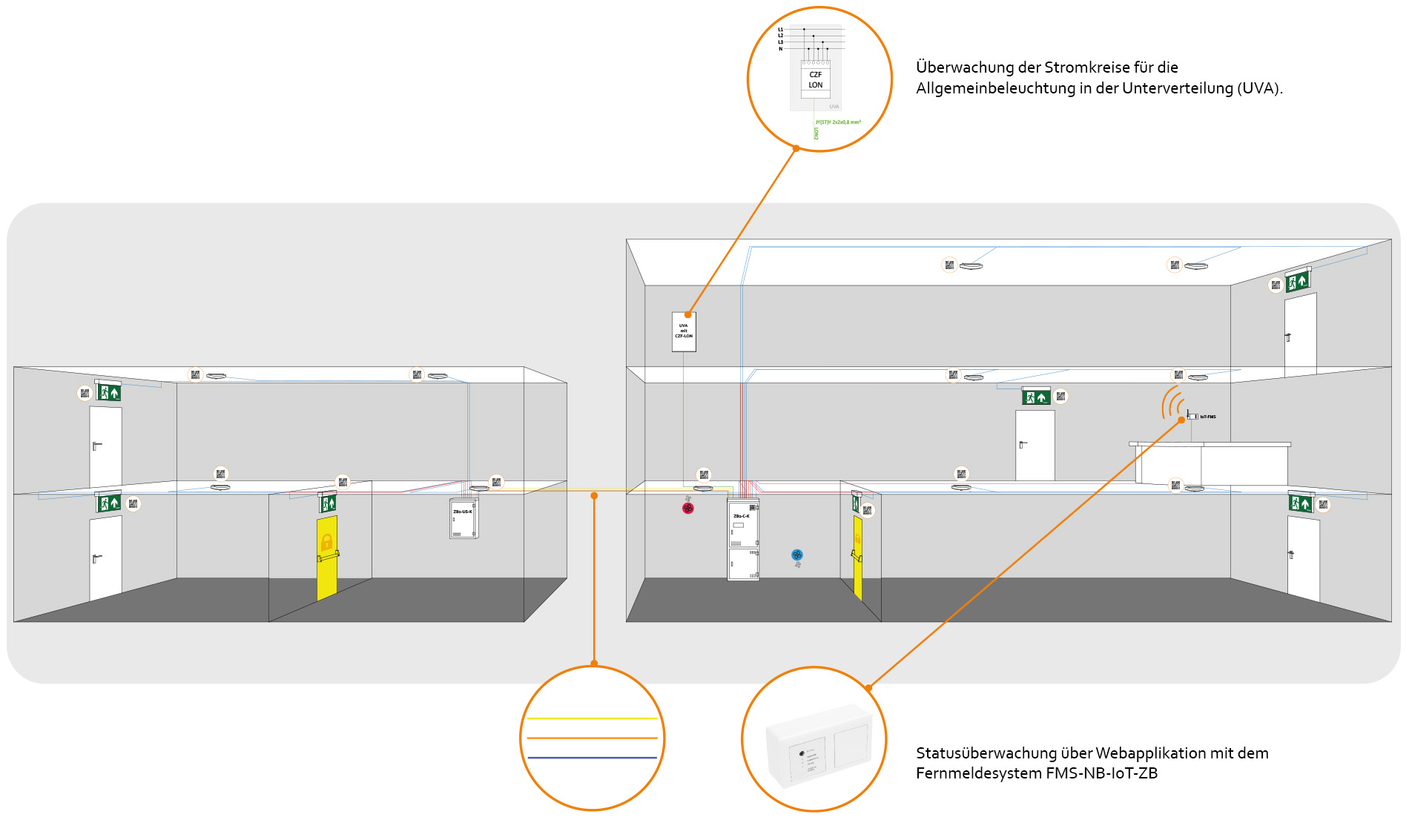
Final circuit in the fire compartment 3x 1.5-4 mm² NYM*
Final circuit in E30 3×1.5-4 mm² NHX*
LON2 bus and 24 V DC min. JY(ST)Y 2x2x0.8 mm²
IoT FMS min. JY(ST)Y 4x2x0.8 mm²
LON3 bus sub-distribution min. JY(ST)Y 1x2x0.8 mm²
E30 DC supply min. NHX 2×1.5 – 16 mm² NHX
AC supply min. NYM 3×1.5 – 16 mm² NYM
(Recommendation E30 NHX)

UNIQUE address
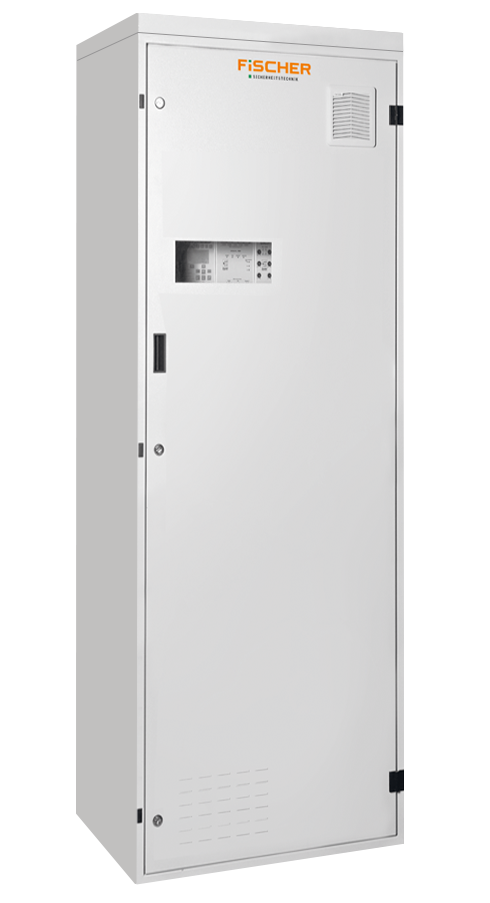
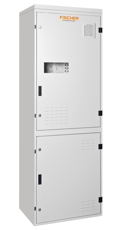
SYSTEM OVERVIEW
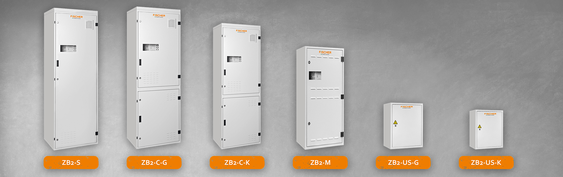
The following systems are available as standard, we implement special solutions individually if possible and in consultation with your specialist consultant in the field:
 |
 |
 |
|
| Technical specifications | |||
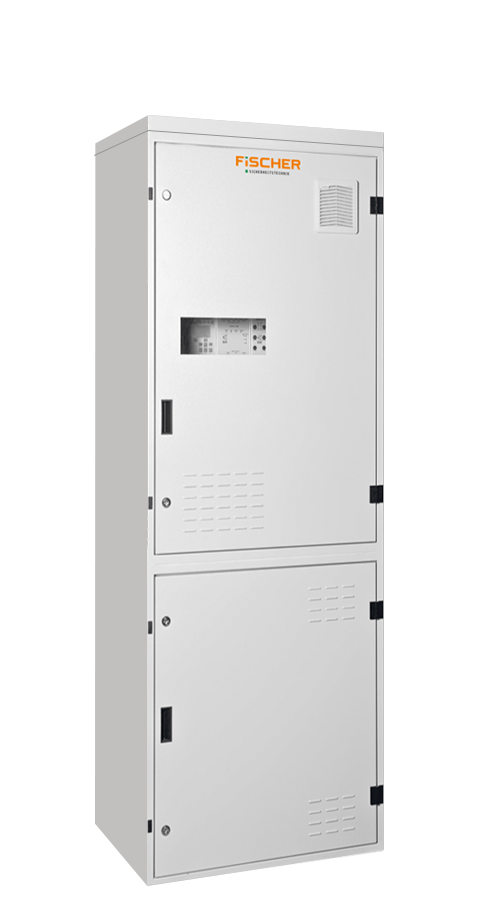
| Article number | ZB2-S | ZB2-C-G | ZB2-C-K |
| Supply voltage | 400 V AC 50 Hz | 230 V AC 50 Hz | |
| Dimensions (W x H x D) | 800 x 2050 x 400 mm | 800 x 2050 x 400 mm | 600 x 1800 x 350 mm |
| Housing material | sheet steel RAL 7035 | ||
| Door stop | on the right | ||
| Type of assembly | stand assembly; pedestal in 10 or 20 cm available separately | ||
| Degree of protection | IP 21 | ||
| Protection class | I | ||
| Cable entry | from above / below above | from above | |
| Opt. # sub-distributions | 6 | 2 | 1 |
| Max. final circuit length | 600 m | ||
| Max. system power | 20 kW | 5,5 kW | |
| Max Battery Capacity Battery Compartment | – | 55 Ah | 33 Ah |
| Max. # final circuits | 80 | 48 | 32 |
| Battery compartment in the cabinet | No | Yes | |
| In the E30 fire protection housing | No | ||
 |
 |
 |
||
| Technical specifications | ||||
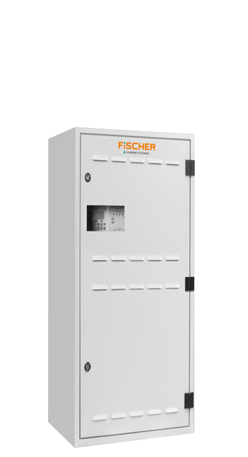
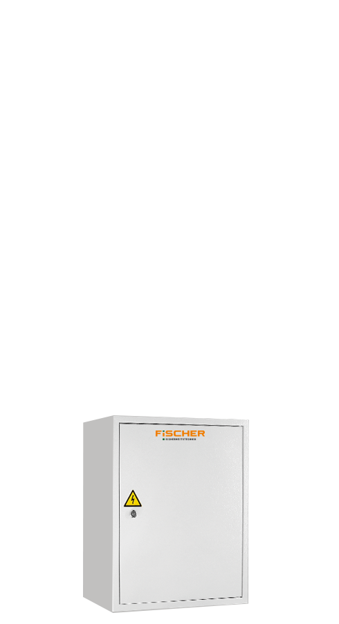
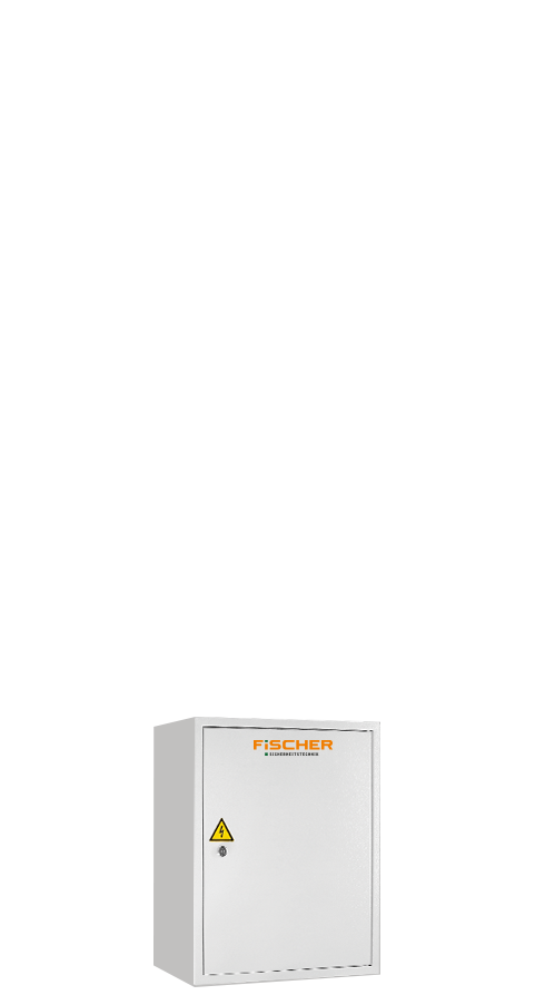
| Article number | ZB2-M | ZB2-US-G | ZB2-US-K | |
| Supply voltage | 230 V AC 50 Hz | 230 V AC 50 Hz | ||
| Dimensions (W x H x D) | 600 x 1200 x 350 mm | 570 x 700 x 300 mm | 420 x 500 x 300 mm | |
| Housing material | sheet steel RAL 7035 | |||
| Door stop | on the right | |||
| Installation | wall mounting | |||
| Degree of protection | IP 21 | |||
| Protection class | I | |||
| Cable entry | from above | |||
| Opt. # sub-distributions | 0 | – | ||
| Max. final circuit length | 600 m | |||
| Max. system power | 1,5 kW | 5,5 kW | 8 kW | |
| Max. battery capacity battery compartment | 20 Ah | – | ||
| Max # final circuits | 24 | 32 | 16 | |
| Battery compartment in cabinet | Yes | – | ||
| In the E30 fire protection housing | Nein | No Optional* | ||
* Type-tested in maximum design; Functional integrity proven by MLAR 5.2.2 section c
Processor MS-L
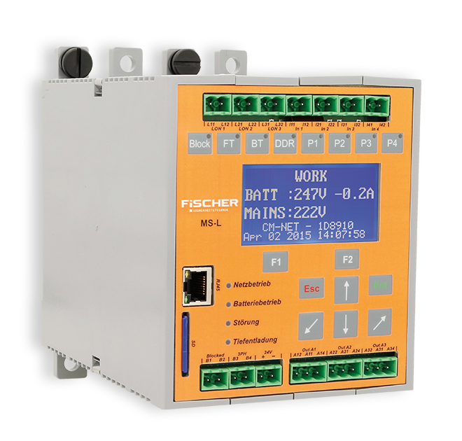
| Technical specifications: | |
| LCD resolution: | 128×64 |
| LED status indicator: | Yes |
| Potential-free outputs: | 3x 24 V, 500 mA |
| Potential-free inputs: | 4 |
| Network connection: | RJ45 |
| Processor of the ZB2 system to manage the individual modules and to coordinate the switching commands. The control module’s front panel buttons and LCD allow the user to configure and monitor the complete system. | |
CIRCUIT MODULE ML-E
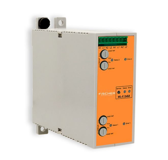
ML-E 2x 6A
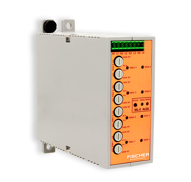
ML-E 4x 3A

ML-E 8x 1,5A
| Technical specifications: | |
| Number of final circuits: | 2 | 4 | 8 |
| Maximum load per final circuit: | 1,5 | 4 | 6 A |
| Maximum final circuit length: | 600 m |
| MiX technology in a final circuit: | >Yes |
| DES support: | Yes |
| Communication to the luminaires: | Via the supply line |
| Individual lamp monitoring with different operating modes of the emergency luminaires for each final circuit. Optimally adaptable for the application depending on the power of the connected luminaires. | |
LON-HUB
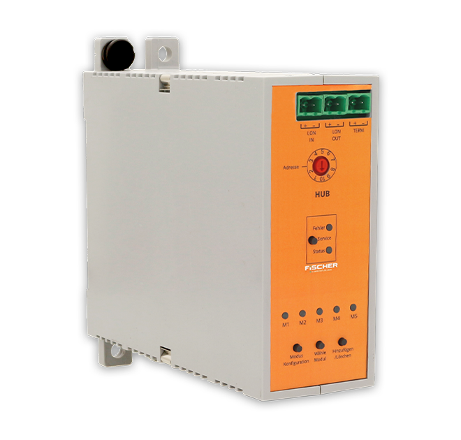
| Technical specifications: | |
| Supply voltage AC: | 230 V AC 50/60 Hz |
| Supply voltage DC: | 216 V DC |
| Integrated power supply: | 24 V DC for up to 5 modules |
| Communication: | LON-BUS |
| The control module for sub-distributions communicates with the ZB2 system via the bus line. An internal 24 V power supply can supply up to five ZB2 modules. | |
BUS NETWORK MONITOR CZF-LON
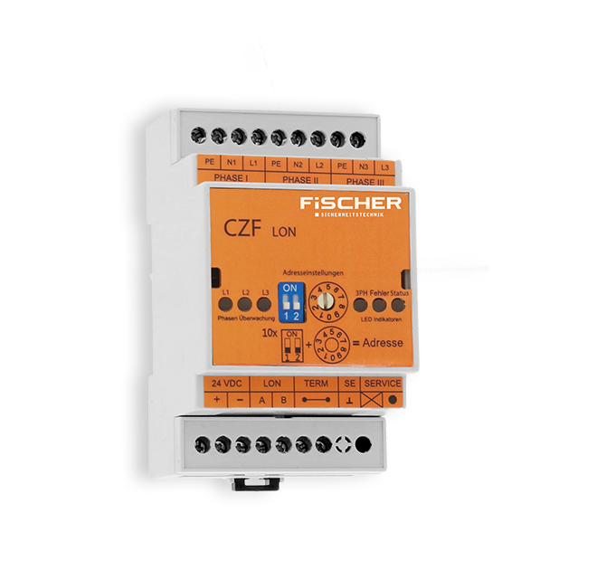
| Technical specifications: | |
| Inputs: | 3x L, N, PE |
| Supply voltage: | 24 V DC via ZB2 system |
| Mains monitor function: | Yes, 3-phase |
| Adjustable switch-back time: | 1-60 min |
| Status LED: | 1x per input |
| Communication: | LON-BUS |
| Maximum bus length: | 900 m |
| Maximum number per system: | 30 bus modules |
TELECOMMUNICATION SYSTEM FMS-NB-IoT-ZB
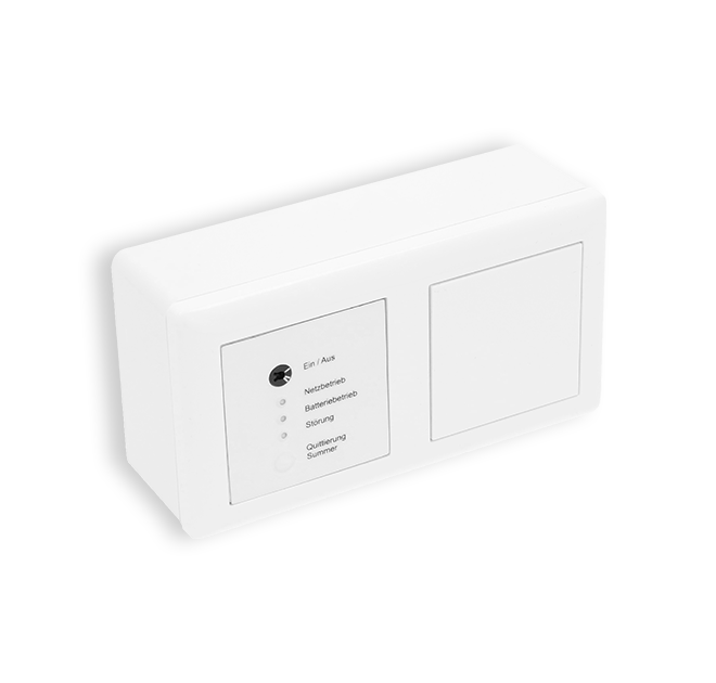
| Technical specifications: | |
| Local status indicator: | 3x LED |
| Dimensions: | 80 mm x 151,5 mm x 45,5 mm |
| Operating voltage: | 24 V DC |
| Network connection: | NB-IoT 3GPP |
| Reporting panel including status forwarding to the |
|
SWITCH REQUEST MODULE LS-230
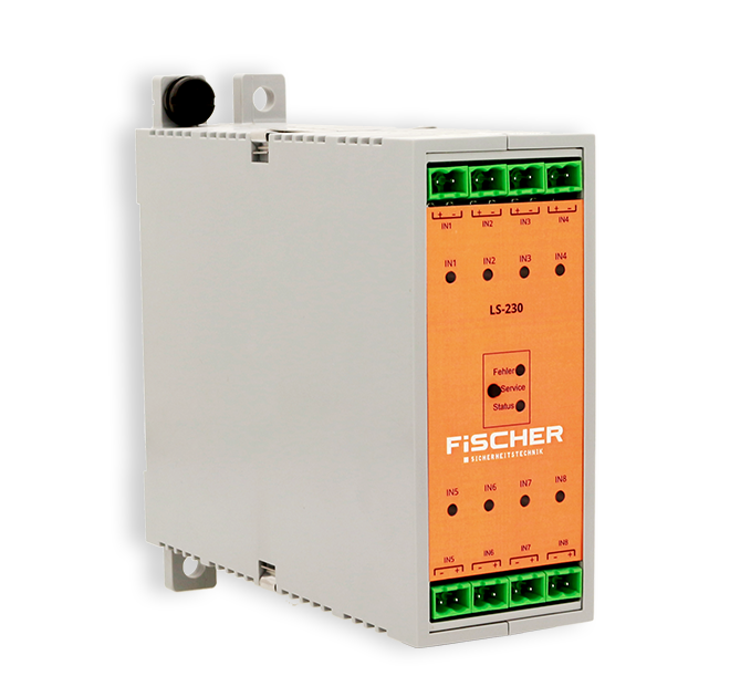
| Technical specifications: | |
| Entrances: | 8 |
| Maximum load: | 230 V AC |
| Output voltage: : | potential-free |
| Status LED: | 1x per input |
| Programmable logic | NO/NC/R-SER/R-PAR |
| Monitoring mains monitor quiescent current loop: | No |
| Adjustable switch-back time: | 1-60 min |
| Maximum number per system: | 10 |
| LS-230 modules are equipped with eight potential-free inputs that can be assigned 230 V AC. | |
SWITCH REQUEST MODULE LS-24

| Technical specifications: | |
| Entrances: | 8 |
| Maximum load: | to be connected potential-free |
| Output voltage: | 24 V DC |
| Status LED: | 1x per input |
| Programmable logic | NO/NC/R-SER/R-PAR |
| Monitoring of mains monitor quiescent current loop: | Yes |
| Adjustable switch-back time: | 1-60 min |
| Maximum number per system: | 10 |
| The input module monitors up to 8 inputs via a 24 V quiescent current loop. Each of these inputs enables individual emergency lighting circuits or lights to be switched. | |
SWITCH REQUEST MODULE ELS-230
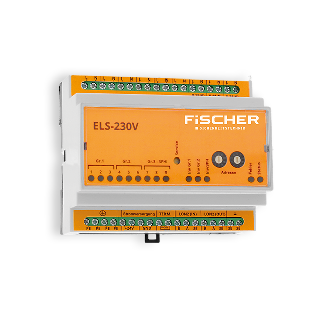
| Technical specifications: | |
| Inputs: | 9 (3 groups with 3 inputs each) |
| Supply voltage: | 24 V DC via ZB2 system |
| Mains monitor function: | Yes, 3-phase |
| Adjustable switch-back time: | 1-60 min |
| Programmable logic: | NO/NC per group |
| Status LED: | 1x per input |
| Communication: | LON BUS |
| Maximum bus length: | 900 m |
| Maximum number per system: | 30 bus modules |
| The ELS-230V sensor module is used to monitor 230 V AC switching signals in the general distribution and to switch on the emergency lighting together with the general lighting. | |
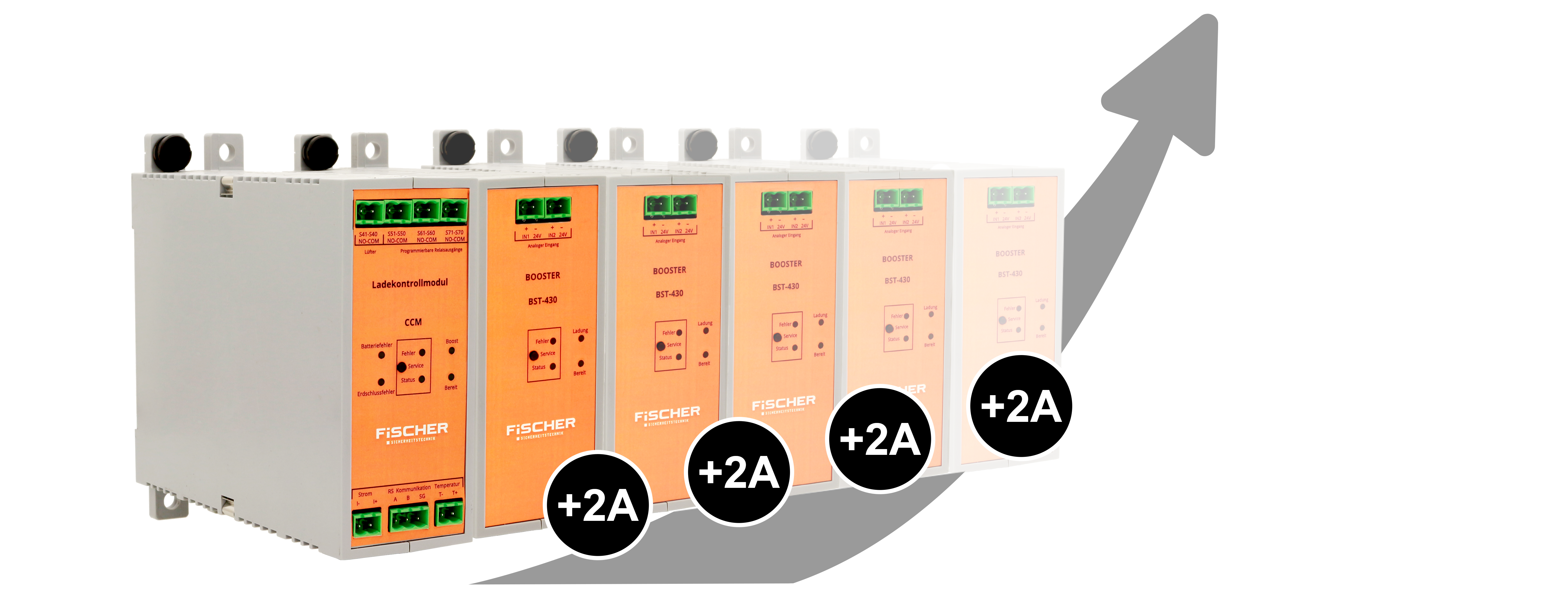
CHARGE CONTROL MODULE CCM + CHARGE AMPLIFIER BST 430
The CCM controls the battery charging process based on the UI characteristic with temperature compensation according to DIN EN 50171 0558-508:2001-11. It regulates the charging algorithm and monitors the condition of the battery. Charging takes place in cooperation with the BST 430 charging amplifier. Up to 16 BST 430 can be controlled by the CCM. During the charging process, the connected charging amplifiers are constantly checked and the power is adjusted accordingly. The module constantly monitors the insulation between the battery circuit and the PE connection. A CCM module and a charging amplifier are always required for operation, further charging amplifiers can be added depending on the battery capacity.

TECHNICAL SPECIFICATIONS
- battery charge control according to EN 50171
- deep Discharge Protection: Default 183.5 VDC
- ground fault monitoring
- optional single block monitoring with IBMS
- fan contact
- 4 programmable relay outputs
- charging voltage and charging current monitoring
- temperature monitoring
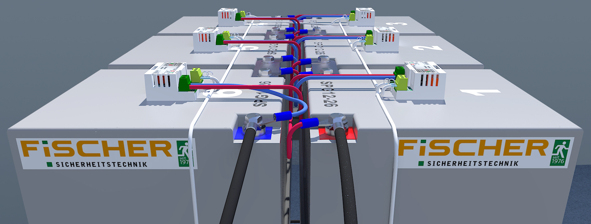
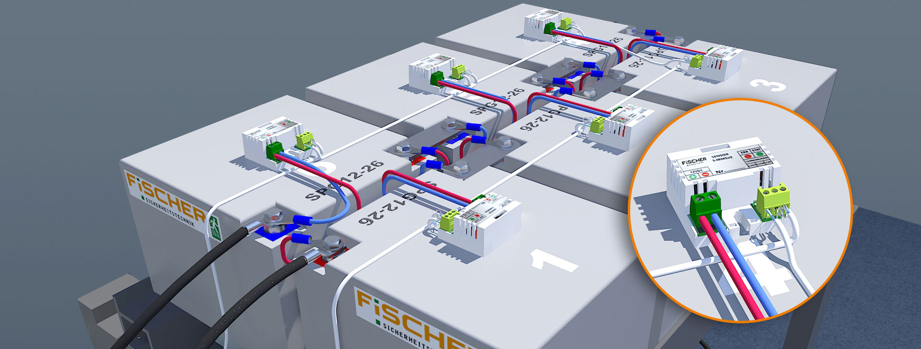
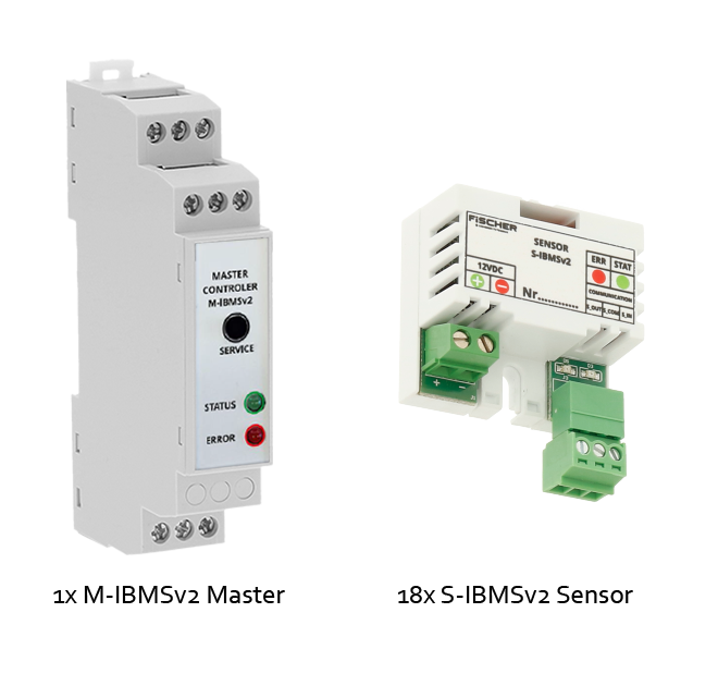
BATTERY STATUS CONTROL SYSTEM IBMS
The single block battery control system IBMS is used for continuous monitoring of battery temperature and voltage. In addition to an optimized battery life, it also guarantees high reliability of the safety power source. The IBMS system consists of individual sensors on each battery and the master unit which collects information from all sensors and relays this to the ZB2 system.
Up to 72 batteries can be monitored. It is possible to define limit values for temperature and voltage individually.
TECHNICAL SPECIFICATIONS
For 18 OGIV blocks 7,2 – 12 Ah
| S-IBMSv2 Sensor | |
| Supply voltage | 5 – 20 VDC |
| Current consumption | 0,25 mA |
| Power consumption | 3,3 mW |
| Housing material | polycarbonatee |
| M-IMBSv2 Master | |
| Supply voltage | 24 V DC |
| Power consumption battery | 1 W |
| Power consumption RS485 transceiver | 0,03 W |
| Insulation voltage | 1500 V |
TECHNICAL SPECIFICATIONS
For 18 OGIV blocks 14 – 55 Ah
| S-IBMSv2 Sensor | |
| Supply voltage | 5 – 20 VDC |
| Current consumption | 0,25 mA |
| Power consumption | 3,3 mW |
| Housing material | polycarbonatee |
| M-IMBSv2 Master | |
| Supply voltage | 24 V DC |
| Power consumption battery | 1 W |
| Power consumption RS485 transceiver | 0,03 W |
| Insulation voltage | 1500 V |
TECHNICAL SPECIFICATIONS
For 18 OGIV blocks 60 – 100 Ah
| S-IBMSv2 Sensor | |
| Supply voltage | 5 – 20 VDC |
| Current consumption | 0,25 mA |
| Power consumption | 3,3 mW |
| Housing material | polycarbonate |
| M-IMBSv2 Master | |
| Supply voltage | 24 V DC |
| Power consumption battery | 1 W |
| Power consumption RS485 transceiver | 0,03 W |
| Insulation voltage | 1500 V |
TECHNICAL SPECIFICATIONS
For 18 OGIV blocks 120 – 200 Ah
| S-IBMSv2 Sensor | |
| Supply voltage | 5 – 20 VDC |
| Current consumption | 0,25 mA |
| Power consumption: | 3,3 mW |
| Housing material | polycarbonate |
| M-IMBSv2 Master | |
| Supply voltage | 24 V DC |
| Power consumption battery | 1 W |
| Power consumption RS485 transceiver | 0,03 W |
| Insulation voltage | 1500 V |
BATTERY TYPES
All the maintenance-free lead-acid batteries we use from the OGi-V series are designed in accordance to DIN EN 50272-2 and DIN EN 50171 and planned with an aging reserve of 25%. The service life is 10 years (+) according to EUROBAT at an ambient temperature of 20 °C. On request, the ZB2 central battery systems can be supplied with maintenance-free and less temperature-sensitive OPzV batteries or low-maintenance OPzS batteries.
BATTERY SIZES (OGI-V) IN BATTERY COMPARTMENT
|
|
|
| ZB2-C-G | ZB2-C-K | ZB2-M |
| 26 Ah | 18 Ah | 12 Ah |
| 28 Ah | 20 Ah | 18 Ah |
| 33 Ah | 28 Ah | 20 Ah |
| 40 Ah | 33 Ah | – |
| 45 Ah | – | – |
| 55 Ah | – | – |


-
PARTNERS


-

-
Social commitment


