ZBN
CENTRAL BATTERY SYSTEM (CBS) FOR EMERGENCY LIGHTING

ZBN – THE NEW EMERGENCY LIGHTING CONSTELLATION
Our new emergency lighting control units now offer the opportunity to install the various components of the emergency lighting system separately from each other. This separation of different categories significantly simplifies planning and installation. For example, in a building with several fire compartments, a submaster can be installed in each fire compartment and connected to the master. This not only reduces the time-consuming installation of expensive E30 cable, but also simplifies maintenance and servicing.
- Optimal design of systems by dividing the safety lighting into submaster areas
- 8 programmable digital inputs for potential-free contacts
- Final circuits using ZBN technology
ZBN MAIN CPU
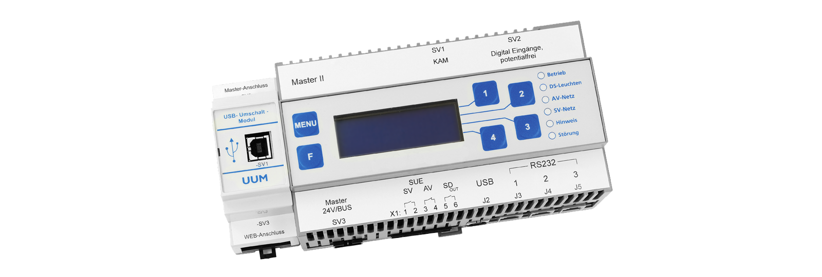
FEATURES
- Optimal design of systems by dividing the safety lighting into submaster areas
- Submaster areas consist of independent systems with their own bus system (module bus)
- Master forms “control centre” and communicates and monitors the submasters via the master bus
- A master bus can be equipped with one master and up to 30 submasters. Each module bus can manage up to 60 modules
- 100-BASE Ethernet port for programming, configuration and management of the system, system configurations can be imported and exported, saving the log book in plain text
- Each Submaster can be equipped with its own spare mains switchover as well as its own battery and charging technology
- 8 programmable digital inputs for potential-free contacts
- 16 freely programmable time and date switches /li>
- Freely programmable fault indication
- Two electrically isolated bus outputs for master and module bus
- Flexible replacement network design via central battery, diesel generator or second network supply possible
FINAL CIRCUITS IN ZBN-TECHNOLOGY
- common operation of 20 luminaires as maintained and non maintained luminaires within one circuit
- each connected luminaire can be configured independently (M/NM)
- single or combined switching of luminaires via switching inputs
- single or combined dimming of luminaires via switch inputs (SMART technology)
- individual light monitoring via the supply line (no separate bus line necessary)
- function monitoring of the bus connection and automatic emergency operation switchover in case of a faulty connection
TECHNICAL SPECIFICATIONS
- USB interface
- Two-pole circuit protection
- Degree of protection: IP 20
- Protection class: I
- Interfaces: USB, LPT
- Colour: RAL 7035
- Input voltage: 230 V / 50 Hz
- Output voltage: 216 V DC
- Operating temperature: 5°C to 35°C
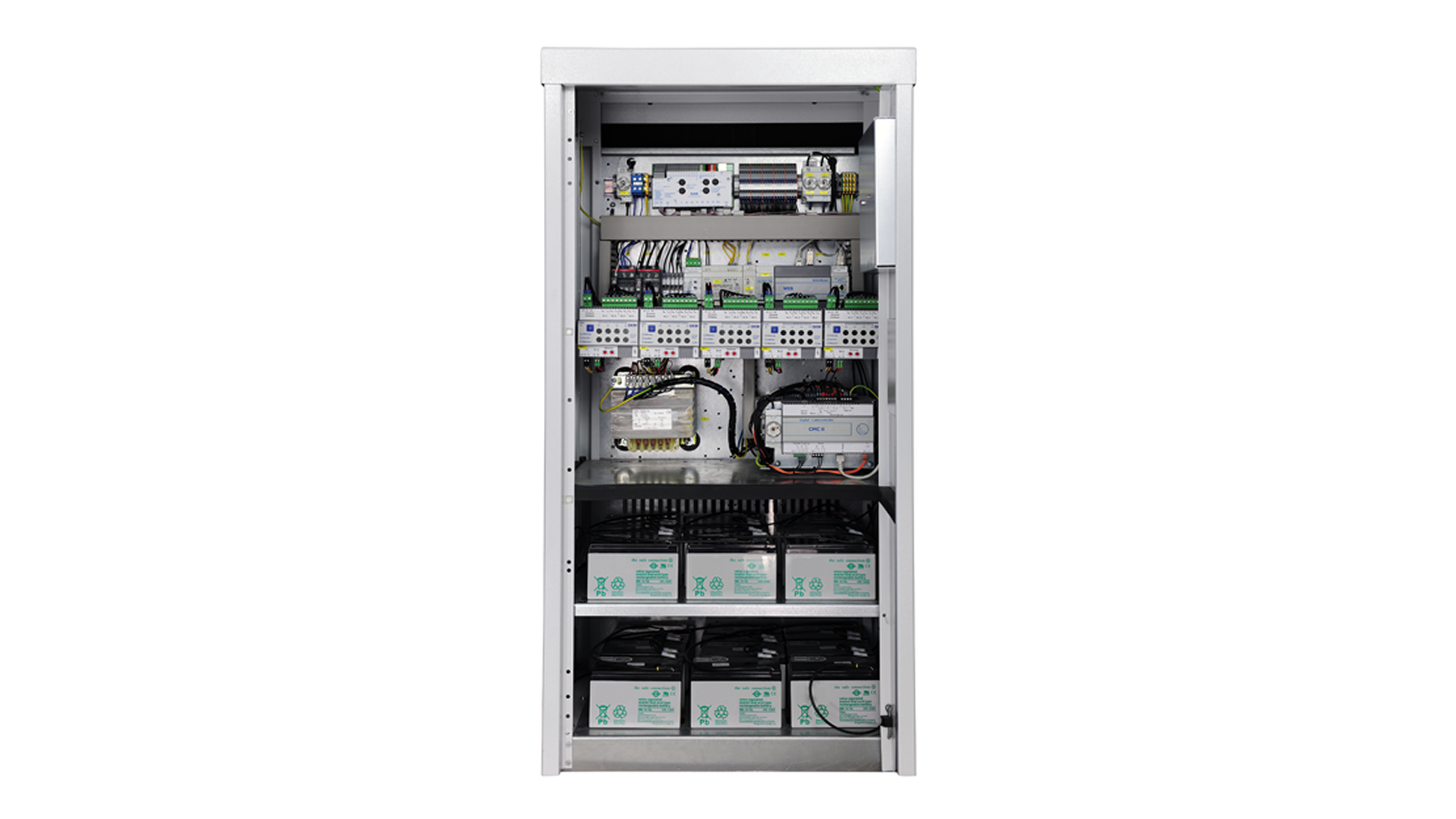
ZBN-K20-INSIDE VIEW
POWER CIRCUIT MODULE SKM

POWER CIRCUIT MODULES SKM
- SKM-M for mixed operation circuits
- SKM-E for single luminaire control
- SKM-N for M- and NM-separated
SENSORIC MODULES

SENSOR MODULES IOM24
- sensor module for processing switching signals
- has 16 inputs for potential-free contacts (odd contacts are charged with 24 V)
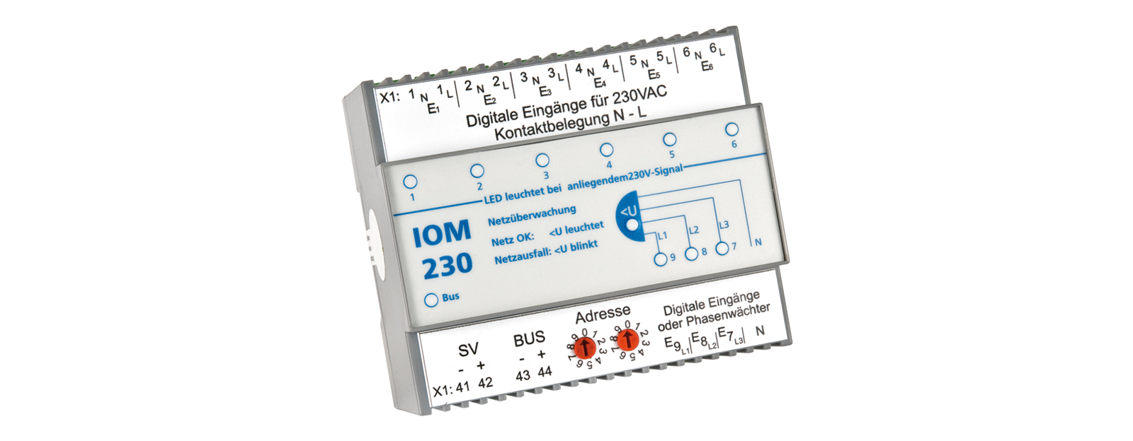
SENSOR MODULES IOM230
- sensor module for processing switching signals
- 9 inputs for monitoring the 230V AC mains or for detecting the switch position of the general lighting installation
- 3 inputs of which can be programmed as phase monitors (single/two-/three-phase)
- Bus network monitor for installation in general lighting distribution (module supply via bus)
LUMINAIRE MONITORING MODULE
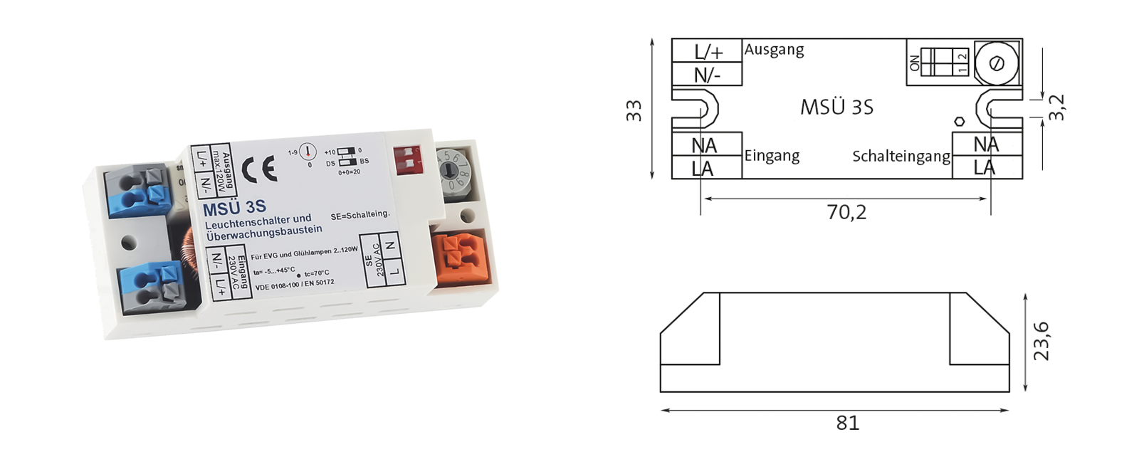
FEATURES
- Luminaires programmable as maintained or non maintained
- AC switching command for all non maintained luminaires in the circuit
- AC luminaire monitoring
- Switching input 230 V AC
- Luminaire address adjustable via rotary encoder
- Does not require a DC back-up network
- Automatic load calibration
- Compatible with DC-modulating electronic ballasts
VISUALISATION
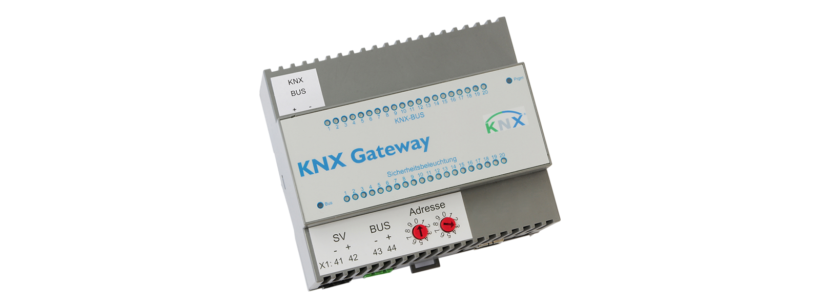
KNX-Gateway
- 20 different commands for the emergency lighting system can be switched from the KNX bus
- 20 different messages from the emergency lighting system can be displayed via the KNX bus
WEB MODULE
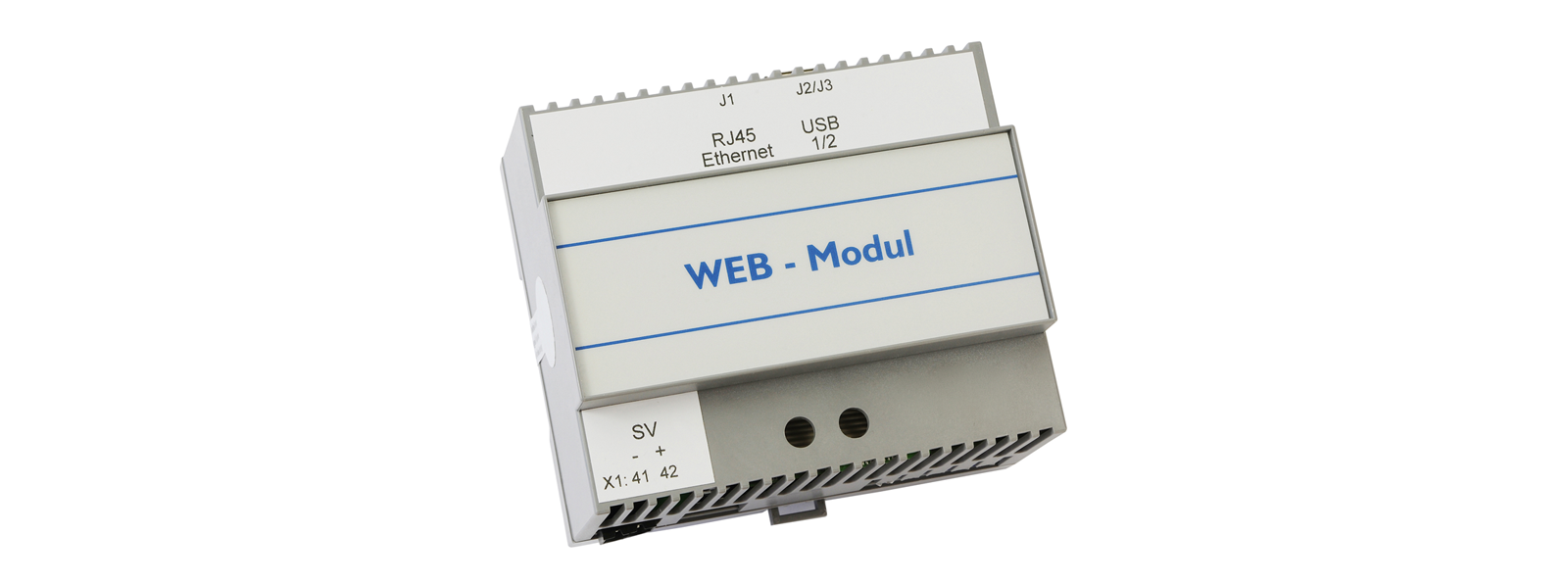
WEB MODULE
- Coloured visualisation of the luminaire type
- Current switching status of each individual luminaire, each circuit and all IOM inputs displayed
- Circuit type is displayed
- Indication of emergency or local emergency operation
- Indication of battery voltage & capacity as well as charge and discharge current
- Programming of time switches
- Starting test operations
- Retrieving test results
WIRING DIAGRAM
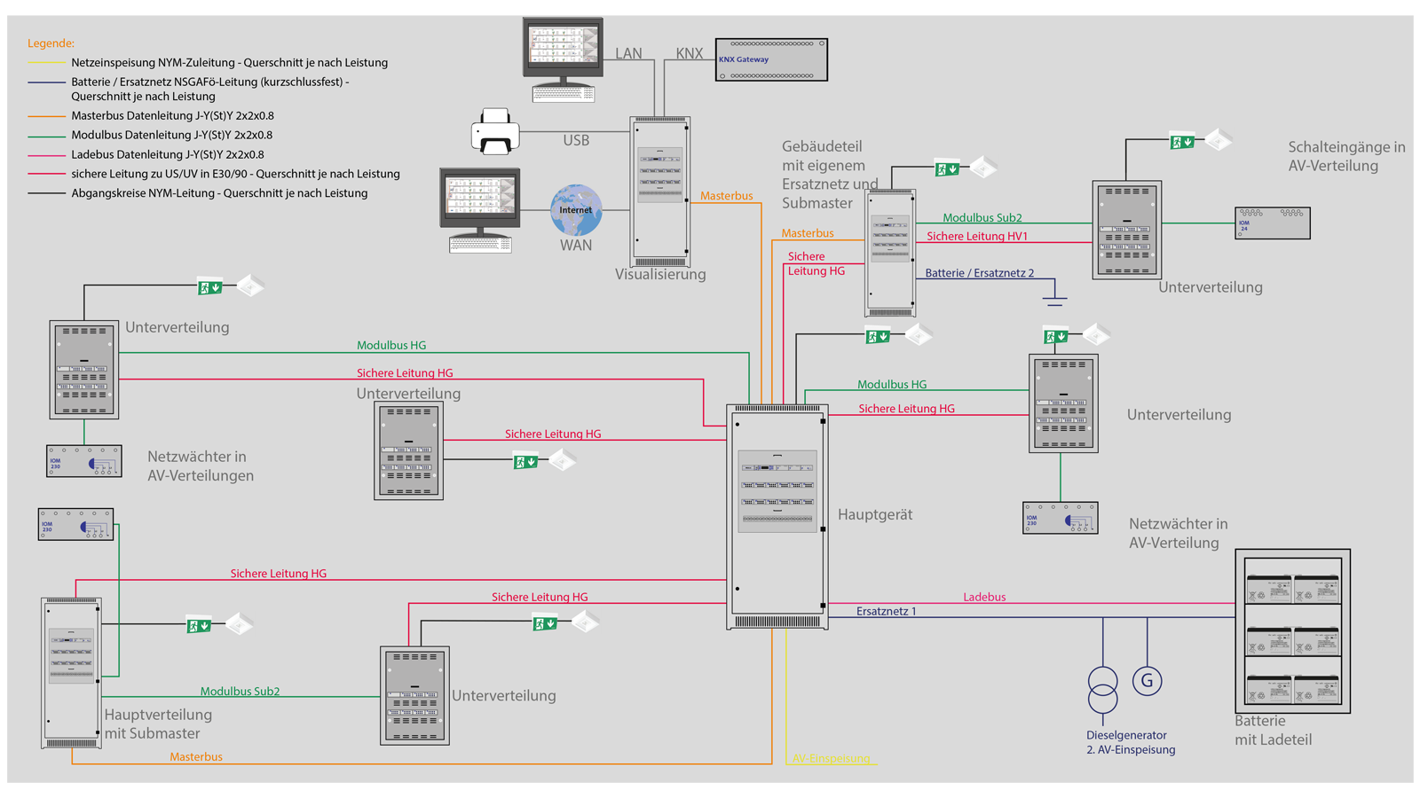
WIRING DIAGRAM
- Two replacement networks in one system
- Separate safe lines between main unit and main distribution
- Master bus connects all masters with submasters
- Module bus is regenerated by each master or submaster
- Charging bus between battery with charging unit and associated master
- Visualization in technical center
Downloads
 ZBN-Datenblatt
-
PARTNERS


-

-
Social commitment


-

FiSCHER Akkumulatorentechnik GmbH
Privacy policy -
Imprint -
General terms and conditions -
Warranty conditions -
maintenance contract terms -
REACH Declaration -
Sitemap